Download
1 / 29
290 likes | 701 Views
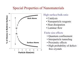
第六章 特殊纳米材料 Special Nanomaterials. Chapter 6. Special Nanomaterials 6.1. Introduction 6.2. Carbon Fullerenes and Nanotubes 碳富勒烯、纳米管 6.2.1. Carbon fullerenes 6.2.2. Fullerene-Derived Crystals 6.2.3. Carbon nanotubes 6.3. Micro and Mesoporous Materials 微、介孔材料

E N D
Chapter 6. Special Nanomaterials 6.1. Introduction 6.2. Carbon Fullerenes and Nanotubes 碳富勒烯、纳米管 6.2.1. Carbon fullerenes 6.2.2. Fullerene-Derived Crystals 6.2.3. Carbon nanotubes 6.3. Micro and Mesoporous Materials 微、介孔材料 6.3.1. Ordered Mesoporous Structures 6.3.2 Random Mesoporous Structures 6.3.3. Crystalline Microporous Materials: Zeolites 6.4. Core-Shell Structures 核-壳结构 6.4.1. Metal-Oxide Structures 6.4.2. Metal – Polymer Structures 6.4.3. Oxide – Polymer Nanostructures 6.5. Organic-Inorganic Hybrids 有机-无机混合物 6.5.1. Class I Hybrids 6.5.2. Class II Hybrids 6.6. Intercalation Compounds 嵌入型化合物 6.7. Nanocomposites and Nanograined Materials 纳米复合、纳米晶材料 6.7. Summary
6.1 引言 除了前面章节介绍的纳米结构和纳米材料,包括纳米颗粒、纳米线、薄膜的基本知识和常规方法以外,有一些重要的纳米材料其合成方法独特,例如碳富勒烯、碳纳米管、有序介孔材料、氧化物-金属核壳结构是本章特别介绍的。 由纳米尺寸的材料构建的块体材料,如纳米晶陶瓷、纳米复合材料,也将在本章中被简要讨论,详细内容请参看相关参考资料。
6.2 碳富勒烯和纳米管Carbon Fullerenes and Nanotubes • 碳是一种奇特的物质,可以是金属性导体(石墨)、宽带隙半导体(金刚石)、聚合物(与氢气反应)。 • 碳可以表现出所有的纳米结构特征,即零维纳米粒子、一维纳米线、二维石墨层状结构、以富勒烯分子为单元构建的三维纳米块体材料。 • 碳富勒烯通常指由60个碳原子组成的对称的二十面体的分子,但也包括大分子量的富勒烯Cn( n>60 ),如C70、C76、C78、C80、和更大的富勒烯,它们具有不同的几何结构。 • 这些碳分子家族命名为富勒烯,是因为其结构与建筑师R. Buckminster Fuller设计和建造的网格球顶相似,然而“巴克明斯特富勒烯”或“巴克球”是特指C60分子,它是研究最多的一种。
橄榄球状C70分子 20面体C60分子 拉长的橄榄球状C80分子 20面体C80分子 碳富勒烯分子结构 Figure 6.1. (a) The icosahedral C60 molecule. (b) The C70 molecule as a rugby ball-shaped molecule. (c) The C80 molecule as an extended rugby ball-shaped molecule. (d) The C80 molecule as an icosahedron. [M.S. Dresselhaus and G. Gresselhaus, Annu. Rev. Mater. Sci. 25, 487 (1995).]
C60中的化学健、制备方法 • C60中的60个碳原子位于对称去顶二十面体的顶点、每个位置等效。但每个碳原子的3个键是不等效的,碳原子的4个价电子用于形成三个化学键,有两个单键和一个双键。 • C60分子二十面体中,有20个六边形面和另外12个五边形面,一个分子直径为7.10 Å。 • C60中临近2个碳原子的平均间距为1.44 Å(与石墨的碳原子间距1.42 Å几乎相同)、每个碳原子与其它碳原子呈三角形连接(与石墨中的连接方式一样)。 富勒烯的制备方法: • 电弧放电法:在约200 torr的He气氛下,石墨电极间电弧放电法。两电极接触点处产生的热量将碳蒸发形成烟尘,在反应器的水冷壁上凝结。放电产生的碳灰中包含多达~15 %富勒烯,其中C60(~13 %)、C70(~2 % )。 1990年,Krätschmer等首次演示这种实验。 • 富勒烯从烟尘中分离:根据它们的质量,采用液相色谱和使用一种溶剂(如甲苯)。 • 富勒烯的生长机理还没有一个明确的认识。由于C60分子独特性、以及具有的各种不同的化学反应能力,富勒烯化学是一个非常活跃的研究领域。
手性角 单壁碳纳米管 • O点和A点在石墨层上是晶体学等效,在此X轴与蜂窝晶格的一侧平行。O点和A点可用矢量Ch = na1 + ma2连接,其中a1和a2是石墨片层蜂窝晶格的单位矢量。 • 从O、A点画出Ch线的法线,得到直线OB和AB’。如果将OB重叠到AB ‘上,就可以得到碳原子构成的圆柱体,其两端用半个富勒烯的覆盖,这就是纳米管。它可以用整数(n, m)表示。 Figure 6.2. The chiral vector OA or Ch = na1 + ma2 is defined on the honeycomb lattice of carbon atoms by unit vectors a1 and a2 and the chiral angle with respect to the zigzag axis. Along the zigzag axis, = 0. Also shown is the lattice vector OB = T of the one –dimensional nanotube unit cell. The rotation angle and the translation (not shown) constitute the basic symmetry operation R = (|) for the carbon nanotube. The diagram is constructed for (n,m) = (4,2). The area defined by the rectangle (OAB’B) is the area of the one-dimensional unit cell of the nanotube. [M.S. Dresselhaus, Annu. Rev. Mater. Sci. 27, 1 (1997).]
从实验的角度看,用直径dt = Ch/、手性角,来表示碳纳米管更方便。 根据不同的手性角,单壁碳纳米管可以有三个基本的几何形状: (a)= 30,扶手椅形 (b)= 0,锯齿形 (c)0 < < 30,手性 Figure 6.3. Schematic models for single-wall carbon nanotubes with the nanotube axis normal to (a) the = 30 direction (an armchair (n,n) nanotube); (b) the = 0 direction (a zigzag (n,0) nanotube); and (c) a general direction OB (see Figure 6.2) with 0 < < 30 [a chiral (n,m) nanotube]. The actual nanotubes shown in the figure correspond to (n,m) values of (a) (5,5), (b) (9,0), and (c) (10,5). [M.S. Dresselhaus, G. Dresselhaus, and R. Saito, Carbon 33, 883 (1995).]
碳纳米管的发展 • 1991年,Iijima用碳阴极电弧放电第一次合成了碳纳米管;而实验发现单壁碳纳米管是在1993年;1996年发现了更有效的合成路线,即激光蒸发石墨制备单壁碳纳米管的有序阵列。目前,碳纳米管可用电弧蒸发、激光烧蚀、热解、气相沉积、电化学方法等方法来制备。 • 在大多数碳纳米管有一个“开放式端口”,这样来自气相的碳原子可以连贯地沉积和进入结构中。开放的端口也可以由一个高电场、相对于有序终端的熵作用、或金属团簇的存在来维持。 • 电弧放电中电场的存在被认为可以促进碳纳米管的生长。 • 少量的过渡金属粉末,如Fe、Co、Ni,有利于单壁纳米管的生长。
气态C原子 内聚能 非晶态碳 纳米管塑性拉伸能 金属催化剂 石墨卷曲能 纳米管 石墨 纳米管生长中的能量 • “食物链”:金属催化剂“吃掉”碳原料,在纳米管的末端不断提供“消化的食料”,促进纳米管的生长。 • 不同碳原料具有较大的内聚能,而用于卷曲石墨形成纳米管的能量、纳米管塑性拉伸的能量较低。 Figure 6.4. “Food chain” illustrates how the metal (Ni/Co) cluster is able to eat essentially any carbon material it encounters and feed the digested carbon bits to the growing end of the nanotube. The vertical axis shows the cohesive energy per atom for the different forms of carbon consumed in nanotube growth. The energy cost for curving the graphene sheet into the cylinder of the (10,10) tube is only 0.045 eV, or 0.08 eV nm2/d2 for a tube of any diameter d. The elastic stretching of a tube by 15% adds approximately 0.66 eV per atom above the graphene. [R.E. Smalley and B.I. Yakobson, Solid State Commun. 107, 597 (1998).]
光纤表面生长 弯曲表面垂直生长的纳米管 碳纳米管有序阵列 • 用化学气相沉积法,直接将Fe纳米粒子嵌入在介孔SiO2基体中,首次证实了碳纳米管阵列的生长。 • 研究发现垂直碳纳米管阵列的直径、生长速度、密度,依赖于催化剂的尺寸。 • 等离子体诱导下的碳纳米管阵列,可以在等高表面生长,其生长方向总是垂直于基板表面。 Figure 6.5. (a) An SEM micrograph showing the radially grown nanotubes on the surface of a 125 m-diameter optical fiber. (b) A close-up micrograph showing the conformally perpendicular nature of the nanotube grown on the fiber. (c)-(f) are examples of nonplanar, complex surfaces where nanotubes can be conformally grown perpendicular to the local surface. [C. Bower, W. Zhu, S. Jin, and O. Zhou, Appl. Phys. Lett. 77, 830 (2000).]
热生长 等离子体生长 电场作用下的纳米管生长 • 直线排列纳米管是由等离子体环境下、基板表面施加的自偏压电场所引起。直流偏置可以促进碳纳米管阵列的成核和生长。 • 无等离子体的条件下,纳米管的线性排列终止,“直”碳纳米管的等离子生长向 “曲”碳纳米管的热生长平稳过渡。 Figure 6.6. (a) An SEM micrograph and (b) a schematic showing the straight/curled nanotube structure produced by an alternating plasma and thermal process (a 2 min plasma process followed by a 70 min thermal process), indicating both the field induced alignment effect and the base growth mechanism. (c) TEM micrograph showing a bundle of nanotubes with the upper portion straight and the lower portion curled. [C. Bower, W. Zhu, S. Jin, and O. Zhou, Appl. Phys. Lett. 77, 830 (2000).]
碳纳米管的催化生长机制 • 碳纳米管的催化生长机理:与纳米线、纳米棒的VLS生长机制类似。Baker和Harris提出了催化碳纤维增长的模型,即碳原子溶解到金属液滴,然后扩散到生长表面并沉积下来,生长出碳纳米管。 • 催化生长的优点:使用标准的光刻蚀技术,比较容易制备出有图案的碳纳米管膜,可在有、无基板的条件下都生长出碳纳米管阵列。过渡金属催化剂协助下的CVD碳纳米管生长法,可以成为规模化生产的方法。CVD还可以使碳纳米管的生长温度很低,如700 C 或 800 C;生长的碳纳米管结晶度较差,但可以通过在氩气下的高温热处理(2500 – 3000 C)来解决这个问题。 • 另一种碳纳米管生长机理:假定碳纳米管是封闭端口的,碳的形核中心在气相生长碳纤维上,通过在碳纳米管顶部附近的五边形吸收C2二聚体而生长,后经变形成为一个碳六边形,加入纳米管并导致管的生长。 • 顶端生长:PECVD、热解生长等 • 基底生长:Fe催化CVD垂直生长碳纳米管阵列
碳纳米管的净化、性能、应用 • 几乎所有的合成方法都会出现碳纳米管与其它碳材料混合,如无定形碳、碳纳米粒子等,因此,净化是必需的,以获得纯净的纳米管产品。 • 气相法:通过氧化过程,气相中去除纳米颗粒和无定形碳,这也会蒸发掉一些小直径碳纳米管。 • 液相法:使用高锰酸钾potassium permanganate, KMnO4液相处理,去除纳米粒子和其它碳形式。这种方法可保留大部分碳纳米管,与气相净化相比具有较高的产率,但管的长度会缩短。 • 插入法:碳纳米管由于具有封闭的笼形结构,不与CuCl2-KCl反应,而其它如碳纳米粒子等与此反应,可通过后续的化学反应去除这类插入物质。 • 碳纳米管的性能及潜在应用: • 输运性能:Langer等首先研究,并由许多研究小组完成实验测试。 • 力学性能:石墨中的C-C是最强的键;TEM观察表明,碳纳米管柔韧,弯曲时不易被折断。 • 导热性能:单个碳纳米管的导热性远远高于石墨或块体碳纳米管。 • 潜在应用:在催化、储存氢气或其它气体、生物细胞电极、量子电阻、纳米电子和机械设备、电子场发射及扫描探针尖端、流量传感器、纳米复合材料。
6.3微、介孔材料Micro and Mesoporous Materials • 根据国际理论和应用化学联合会(IUPAC)的分类,根据其孔径,多孔固态材料可分为三类: • 微孔microporous(d < 2 nm):几乎所有的沸石zolites及其衍生物 • 介孔mesoporous(2 nm < d < 50 nm):表面活性剂模板surfactant template mesoporous materials • 大孔macroporous(d > 50 nm):大多数干凝胶和气凝胶
有序介孔结构 • 有序介孔材料:以自组装表面活性剂为模板、同时在其周围进行溶胶-凝胶凝结过程来制备 • 特点:均一的尺寸和孔的形状,直径为3纳米 ~ 几十纳米,长度达到微米级,而且往往有一个非常大的孔体积(高达70 % )和非常高的比表面积(> 700 m2/g) • 技术应用:可作为载体、吸附剂、分子筛、纳米级化学反应器等
表面活性剂 • 表面活性剂是有机分子,由不同极性的2部分组成:一端是烃(碳氢)链(通常称为聚合物的尾巴),无极性、疏水、亲油;另一端是极性、亲水性(通常称为亲水头)。表面活性剂富集在溶液表面、或者水与碳氢化合物溶剂的界面处,亲水头转向水溶液,从而减少表面或界面能。这是自发形成,热力学有利。 • 表面活性剂分4大类: • 阴离子型anionic:磺化化合物R—SO3Na,和硫酸盐化合物R—OSO3Na,R是一个由11~21碳原子组成的烷基链。 • 阳离子型cationic:一个烷基疏水尾部和甲基铵离子化合物头,如十六烷基三甲基溴化铵( CTAB,C16H33N(CH3)3Br)、十六烷基三甲基氯化铵( CTAC,C16H33N(CH3)3Cl)。 • 非离子型nonionic:溶解于溶剂时,不分解成离子。其亲水头是一个极性基团,如乙醚(R-O-R)、酒精(R-OH)、羰基(R-CO-R)、胺(R-NH-R)。 • 两性型amphoteric:其性质即类似于非离子型、也像离子型表面活性剂。例子,三甲基铵乙内脂和磷脂。
γ 电解液 Electrolytes γ0 溶液的表面张力 Surface tension 有机溶质 Organic solutes 正好覆盖溶液全部表面 表面活性剂 Surface active solutes Critical Micellar Concentration 临界胶束浓度 浓度 C2 (C.M.C) 表面活性剂 vs. 溶液表面能 Figure 6.7. Effect of different solutes on the surface tension of a solution. Surfactants, or surface active molecules will preferably allocate at the surface, resulting in a decrease in surface tension with an increasing concentration till the critical micellar concentration, or CMC is reached. Further increase in surfactant concentration will not reduce the surface tension.
疏水尾 Hydrophobic tail 亲水头 Hydrophilic head 阴离子型表面活性剂 Anionic surfactant molecule 相反电荷离子 Counterion A 首先形成球形胶束 C 六角形堆垛圆柱形胶束 Hydrophilic head Hydrophobic tail B 单个圆柱形胶束 D 薄层状胶束 + + + + + + + + + 胶 束 的 形 成— 表面活性剂浓度 > C.M.C Figure 6.8. (a) Spherical micelle forms first as the concentration of surfactants is above the CMC. (b) Individual cylindrical micelle forms at the concentration of surfactants increases further. (c) Further increased concentration of surfactants results in the formation of hexagonally packed cylindrical micelles, (d) Lamellar micelles would form when the concentration of surfactants rises even further.
OH OH OH Si Si Si HO HO HO OH OH OH O O O O O O O O O O O O O O O O O O O O O OH OH Si Si Si Si Si Si Si Si Si Si Si Si Si Si Si Si Si Si OH OH OH OH OH OH OH OH O O O OH HO HO OH OH HO HO OH HO OH OH HO OH OH 有序介孔材料的形成—胶束作为模板 在胶束周围,无机前驱物经水解、缩合反应形成框架 Figure 6.9. Schematic showing the process of the formation of mesoporous materials. Surfactant molecules form cylindrical micelles with hexagonal packing, while inorganic precursors 无机前驱物form a framework around the micelles through hydrolysis 水解and condensation reactions 缩合反应.
复合金属氧化物介孔材料的物理性能 Table 6.1. Physical properties of mesoporous complex metal oxides • 除了硅和铝硅酸盐以外,其它各种氧化物也可以形成有序介孔结构,已进行了大量关于合成有序介孔复合金属氧化物的研究。 • 复合金属氧化物也称为混合金属氧化物,拥有许多重要的物理性质,有利于广泛的应用,特别作为现代化工产业中的非均相催化剂。
TiO2 ZrO2 Nb2O5 SiAlO3.5 TiO2 介孔材料的TEM Figure 6.10. TEM micrographs of two-dimensional hexagonal mesoporous TiO2 (a, b), ZrO2 (c, d), Nb2O5 (e) and SiAlO3.5 (f). a, d Are recorded along the [110] zone axis and b, c, e, f along the [001] zone axis, respectively, of each material. Insets in a and c are selected-area electron diffraction patterns obtained on the image area. g, Bright-field TEM image of a thin slice of the mesoporous TiO2 sample. h, Dark-field image obtained on the same area of the same TiO2 sample. The bright spots in the image correspond to TiO2 nanocrystals. The images were recorded with a 200 kV JEOL-2000 TEM. All samples were calcined at 400 °C for 5 h in air to remove the block copolymer surfactant species. [P.D. Yang, D.Y. Zhao, D.I. Margoless, B.F. Chemelka, and G.D. Stucky, Nature 396, 152 (1998).]
无序介孔结构 Random Mesoporous Structures—溶胶-凝胶工艺制备法 • 介孔结构制备方法:滤取玻璃分离相、酸性电解质中薄金属箔片的阳极氧化、辐射跟踪刻蚀、溶胶-凝胶工艺。 • 溶胶-凝胶法制备的介孔材料,分为两种类型: • 干凝胶 xerogel:室温条件干燥,孔隙率约为50 %,孔径为几个nm • 气凝胶 aerogel:超临界干燥,孔隙率75 %~99 %,孔径为几个nm 在溶胶-凝胶工艺中,前驱体分子进行水解、缩合反应形成纳米团簇。通过“老化”将纳米团簇形成凝胶,这是溶剂和固体物质构成的三维渗透网络。溶剂在随后干燥过程中被去除,凝胶网络将由于毛细管力(Pc)的作用而部分坍塌,而坍塌的凝胶网络将促进表面凝结,使残余凝胶网络得到强化,因此不会形成致密结构。 干凝胶: 拉普拉斯方程给出Pc: LV — 气-液界面的表面能;— 液体在固体表面上的润湿角;R1、R2 — 液-气相弯曲表面的主要半径
溶胶-凝胶法合成的多孔氧化物的性能Table 6.2. Structural properties of sol-gel derived porous materials
P (MPa) 压力 Path II Path I Solid Liquid 7.37 临界点 Critical point Triple point Vapor 温度 31.0 T (˚C) 干燥CO2溶剂 2 种常见的超临界干燥途径 1930年代初期首次制得,1996年代开始应用。气溶胶制备中,为了加强凝胶网络,湿凝胶需要老化一段时间。在高压器中,温度和压力在溶剂的超临界点以上,此时溶剂将从凝胶网络中去除。在超临界点以上,固体和液体之间的区别消失,因此,毛细管力不再存在。其结果是,凝胶网络的高度多孔结构得以保存。这种气凝胶的孔隙度高达99 % ,表面积超过1000 m2/g。 气凝胶: 超临界干燥过程:在温度、压力都高于溶剂的临界点的压力容器中加热湿凝胶,然后保持温度高于临界点,减小压力,慢慢地排出液相。 Figure 6.11. An example of a possible supercritical drying path of CO2. There are two practical approaches: (a) increase the pressure above the supercritical point of the solvent and then heat the sample above supercritical temperature while maintaining the pressure constant, and (b) increase the pressure above the vapor pressure at room temperature and then increase both temperature and pressure simultaneously by heating.
常见溶剂的临界点参数 Table 6.3. Critical point parameters of common solvents
晶态介孔材料:沸石 Zeolite • 1756年最早被发现,有34 种天然沸石、近100种合成的沸石。具有分子尺寸的均匀孔隙和三维框架结构,孔隙直径 ~ 0.3 - 1 nm,孔隙容量 ~ 0.1 - 0.35 cc/g。 • 沸石是晶态的铝硅酸盐,成分为M2/nO.Al2O3.xSiO2.yH2O(n为移动阳离子的价态,Mn+,x 2)。由TO4四面体组成的(T为四面体原子,即Si、Al) ,每一个氧原子被相邻四面体共享,从而导致所有沸石框架内O/T比率等于2。空间框架是由4角连接TO4四面体构成。 • 沸石具有广泛的应用,例子包括催化剂,吸附剂,分子筛。
沸石中的亚单元和笼状结构 Figure 6.12. Some subunits and cages that recur in several framework types of zeolites; each cross point is designated to a TO4 tetrahedron where T is a metal such as silicon or aluminum. [L.B. McCusker and C. Baerlocher, in Introduction to Zeolite Science and Practice (2nd ed.), eds., H. van Bekkum, E.M. Flanigen, P.A. Jacobs, and J.C. Jansen, Elsevier, Amsterdam, p.37, 2001.]
(a)SOD框架 (b)LTA框架 2 种沸石框架类型— SOD、LTA Figure 6.13. (a) The SOD framework type, having a body centered cubic arrangement 体心立方排列of or sodalite方钠石cages (see Figure 6.12). (b) The LTA framework type with a primitive cubic arrangement 简单立方排列of -cages joined through single 8-rings (producing a sodalite cage in the center). [L.B. McCusker and C. Baerlocher, in Introduction to Zeolite Science and Practice, 2nd ed., eds., H. van Bekkum, E.M. Flanigen, P.A. Jacobs, and J.C. Jansen, Elsevier, Amsterdam, p. 37, 2001.]