Download
1 / 24
240 likes | 486 Views
Analog Theremin Using Vacuum Tubes and Frequency Detection via Band-pass Filters. Matt Britt, Ryan Adams, William Findley Jr., Yuri Yelizarov, James Lewis Georgia Institute of Technology School of Electrical and Computer Engineering March 4, 2008 and March 6, 2008.

E N D
Analog Theremin Using Vacuum Tubes and Frequency Detection via Band-pass Filters Matt Britt, Ryan Adams, William Findley Jr., Yuri Yelizarov, James Lewis Georgia Institute of Technology School of Electrical and Computer Engineering March 4, 2008 and March 6, 2008 Team Theremin
Analog Theremin and Frequency Detector • The Theremin is an electronic musical instrument controlled by interaction with volume and pitch antennae. • The frequency detector is designed to assist new players in playing on the musical scale. • The target customers are musicians. • The projected cost of the Theremin is $550. • The projected cost of the frequency detector is $145. Team Theremin
Theremin: Technical Objectives • Designed using vacuum tubes in order to suit the preference of musicians. • Safe to use. • Dynamic pitch and volume ranges to provide sufficient playability. • Tuning controls to allow adjustments in player stance. • Compatible with standard audio equipment. • Finished case design in a form suitable for a final product. Team Theremin
Theremin: Block Diagram Team Theremin
Theremin: Technical Specifications • Output of the pitch circuit will cover a 30 Hz to 1 kHz range of sound. • Volume circuit will produce a control voltage for the voltage-controlled amplifier. • Power supply circuit will provide two power rails: 6.3 VAC at 2.5 A and 75 VDC at 10 mA. • The output will use a standard audio equipment line-out, max 1.4 Vrms. Team Theremin
Pitch Control Overview • RF signals generated by Colpitts oscillators at ~500 kHz • Mixer is a triode biased in non-linear region • Low-pass filter is a two-pole RC cascade Team Theremin
Pitch Control Circuit Pitch Reference Oscillator Low-pass Filter Mixer Pitch Variable Oscillator Team Theremin
Pitch Control Performance • First versions • High harmonic output • Unable to produce tones below 500 Hz • Smaller effective pitch range • Current version • Near-sinusoidal output from oscillators • Able to produce low frequencies • Strong RF signal difficult to isolate Team Theremin
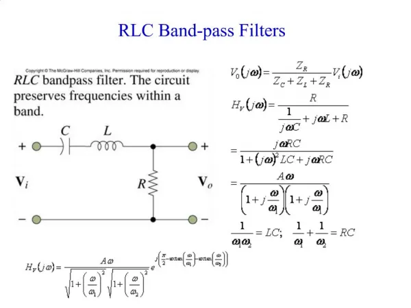
Volume Control Overview • Uses another RF oscillator at 480 kHz • High-Q band-pass filter using ceramic resonator • Peak detector circuit via level shifter and rectifier • Voltage controlled amplifier in form of a differential amplifier Team Theremin
Theremin Design Approach • Research possible circuits • Hand design using published and simulated I-V curves • Simulation using phenomenological triode SPICE model • Imperfect • Model better for “high” plate current Linear amplifier Nonlinear mixer Published plate characteristics for 12AU7A twin triode. Circa 1956. Team Theremin
Frequency Detector Overview • Objective: • Indicate to the user which output is being used by the Theremin. • Problem: • The Theremin produces a wide range, continuous signal. • With most instruments, a user knows exactly what pitch is produced. • The Theremin relies on the musician’s ear and muscle memory. • Solution: • An external system that lights up an LED corresponding to an output frequency produced by the Theremin. • An LED is provided for each pitch of a chromatic scale. Team Theremin
Frequency Detector Block Diagram Team Theremin
Frequency Detector Building Blocks • Gain = (Z1 + Z2)/Z1 • Increasing the impedance Z2 or decreasing the impedance Z1 will increase the gain. • Increasing the impedance Z1 or decreasing the impedance Z2 will decrease the gain. Team Theremin
Frequency Detector Notch Filter Simulation Team Theremin
Frequency Detector: Combining Elements Op Amp Gain: 1000 V/V Input Signal: 1 Vrms Signal Range: 400 Hz – 500 Hz Number of Points: 500 R1 = 10 kΩ RL = 1 kΩ L1 = 3 mH C1 = 43.6 µF Team Theremin
Frequency Detector Simulation Team Theremin
Demonstration Plan • Measure DC voltage of the antennae, should be less than a few millivolts. • Demonstrate pitch range, straight antenna. • Keep volume hand steady and change position of pitch hand. • Demonstrate volume range, loop antenna. • Keep pitch hand steady and change position of volume hand. Team Theremin
Problems: RF Propagation • RF propagation issue: • High power, 5 Vpp, signal coming out of the oscillators may cause coupling and propagation along power rails. • Alleviation: • Careful routing of traces and wiring on PCB and placement of decoupling capacitors. • Reduced signal on DC power rail from 1 V to 10 mV. Team Theremin
Problems: Mixer Design • Nonlinear design issue: • Nonlinear mixer behavior is difficult to predict. • The practical results differ greatly from simulation. • Alleviation: • Trial and error used to get current result. • A curve tracer may be used later. Team Theremin
Project Schedule Team Theremin
Theremin Cost Analysis • Projected sales volume of 10,000 over a four year period. • Three group members working on Theremin portion of project. • The cost of each Theremin unit is $550. Team Theremin
Frequency Detector Cost Analysis • Projected sales volume of 20,000 over a four year period. • Two group members working on frequency detector portion of project. • The cost of each frequency detector unit is $145. Team Theremin
Current Status • Circuit built on tube “breadboard”. • Pitch control circuit works up to the low-pass filter. • Band-pass filter, for volume control circuit, is designed. • Antennae material is decided on. Team Theremin
Questions? Team Theremin