Download
1 / 8
270 likes | 2.45k Views
Band-pass Filters and Resonant Circuits. Resonant frequency. Quality factor. RLC Resonant. At resonance: current is max. Zeq =R current and voltage are in phase. the higher Q, the narrower the resonant peak.. Applications: tuning circuit. Concept Check: ac Circuit Resonance. The current in an RLC series circuit leads the ac voltage source. To bring the circuit to resonance, should the capacitance be increased or decreased? .

E N D
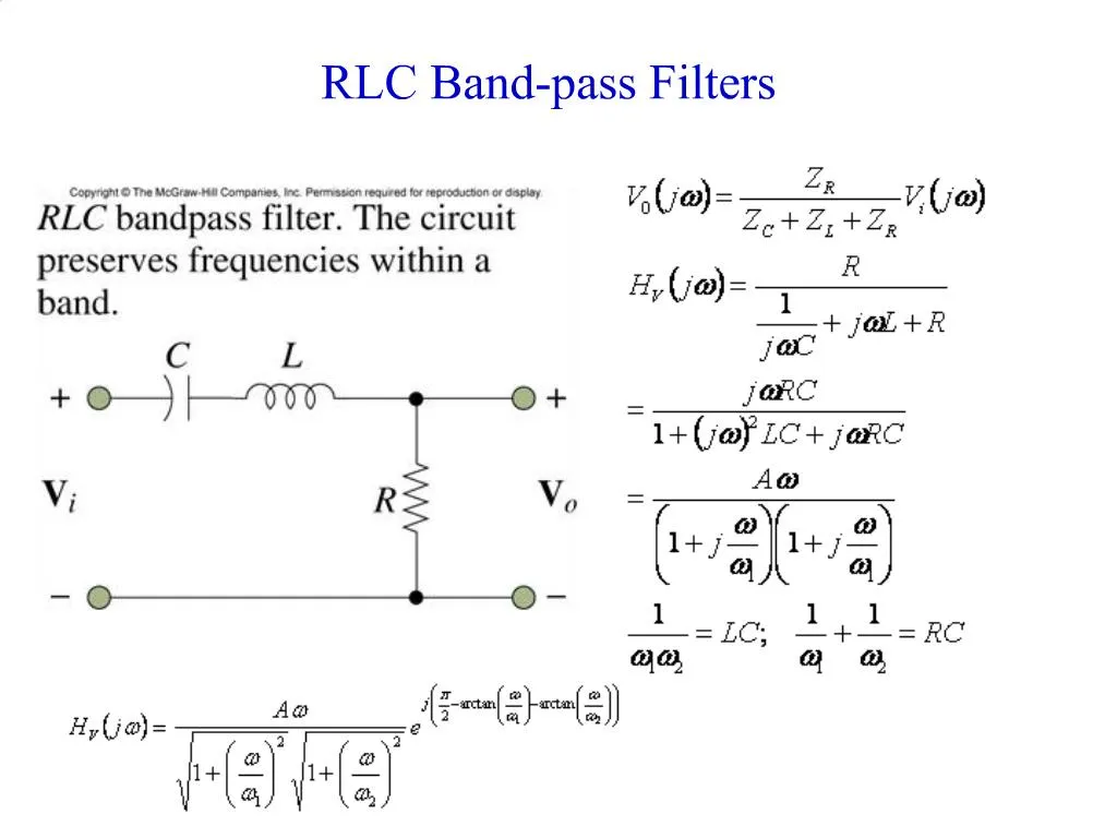
1. RLC Band-pass Filters
2. Band-pass Filters and Resonant Circuits
3. RLC Resonant
4. Concept Check: ac Circuit Resonance
5. Ex: Notch filter, p303
6. Decibel Measure Amplifier gain and filter loss are often specified in decibels (dB), a logarithmic measure of ratios. Most generally dB are specified for power ratios,
power gain�in�dB=�10�log10�(Pout/Pin)
More generally in this course, we are interested in voltage gain;
since P�~�V2, voltage gain�in�dB=�20�log10�|Vout/Vin|
Advantages of decibel measures:
Ease of handling large quantities that can vary over many orders of magnitude.
However, keep this compression firmly in mind! For example, the Richter scale for earthquake intensity is logarithmic -- a 7 on the Richter scale actually has an amplitude 10 times more powerful than a 6, corresponding to a factor of about 31-32 times more energy.
In cascaded amplifier/filter systems, the overall gain is the product of each stage's gain. Since log(A.B)�=�log(A)�+�log(B), if one wishes to consider the overall gain of several stages, one simple adds the gain of each in dB measure.
As we will see below, the frequency dependence of an amplifier or filter is most often summarized on a Bode plot. For a Bode plot, the log of the |gain| is plotted against the log of the frequency. Thus in dB measure the vertical axis becomes a linear axis.
7. Bode Plots
8. Bode Plots: cont.
9. Bode Plot: High-pass filter