Download
1 / 14
310 likes | 586 Views
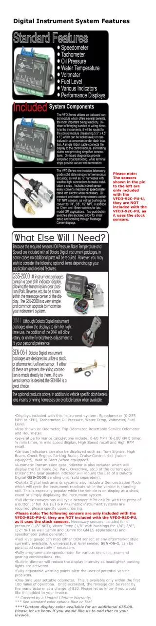
PC-based Biomedical Instrument Larger systems necessitate the design of a dedicated computer system (hard drive, display monitor, elaborate controls).

E N D
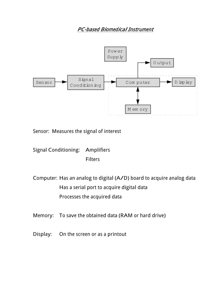
PC-based Biomedical Instrument . Power Suppl y Output Si gnal Di spl ay Sensor Com puter Condi ti oni ng M em ory . Sensor: Measures the signal of interest Signal Conditioning: Amplifiers Filters Computer: Has an analog to digital (A/ D) board to acquire analog data Has a serial port to acquire digital data Processes the acquired data Memory: To save the obtained data (RAM or hard drive) Display: On the screen or as a printout
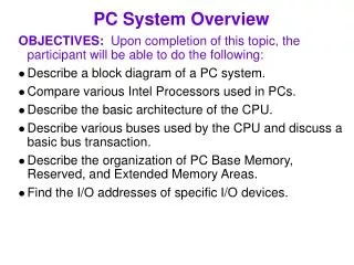
Microcontroller Based Biomedical Instrument 1. A general purpose computer does a lot of things that are unnecessary for some dedicated biomedical instruments 2. A computer is large in size and limits portability 3. Several applications require the use of a dedicated instrument: portable (home measurement devices) or otherwise (ultrasound, MRI, CT, etc.) • Portable systems require the use of a microcontroller • Larger systems necessitate the design of a dedicated computer system (hard drive, display monitor, elaborate controls) . Power Suppl y Si gnal Sensor M i crocontrol l er O utput Condi ti oni ng M em ory .
Microcontroller Based Biomedical Instrument . Power Suppl y Si gnal Sensor M i crocontrol l er O utput Condi ti oni ng M em ory . Microcontroller . M em ory A/D Converter M i croprocessor Seri al Com m uni cati on Interface . Example: MC68HC11 M 68HC Motorola’s general mcu family Motorola HCMOS (high-density complementary metal oxide semiconductor) MC68HC11 family 11
Microprocessors Examples: 8085, 8086, 8088, 80286, 80386, 80486, Pentium The inside of a microprocessor contains hardware that processes the data based on commands from the software. A microprocessor performs • a small set of very simple tasks. • a pre-determined series of steps according to a set of instructions (assembly language) • the operations very quickly All that a microprocessor can do is to do simple standardized operations over and over at a very fast rate, in proper order Digital hardware consists of a few cheap and simple building blocks, cleverly interconnected and repeated over and over again. Digital data (represented by 0s and 1s) are processed by elements called logic gates.
A/D and D/A Converters Analog to Digital: convert analog voltage to a binary representation di gi tal output D0 D1 anal og i nput A/D Converter D2 D3 Timing Signal Digital to Analog: convert a digital word into an analog voltage di gi tal i nput D0 D1 anal og output D/A Converter D2 D3 Timing Signal Parameters to be concerned about: max. voltage level (analog) number of bits (digital) when should it sample
Logic Gates NOT A 0 1 B 1 0 OR A1 0 0 1 1 A2 0 1 0 1 B 0 1 1 1 AND A1 0 0 1 1 A2 0 1 0 1 B 0 0 0 1 NOT: inverts OR: 1 if any of its inputs is 1 0 if all inputs are 0 AND: 1 if all inputs are 1 0 if any of the input is 0
Semiconductors Conductors Semiconductors Insulators Resistors V=IR linear characteristics Passive circuits: contain resistors, capacitors and inductors Active circuits: contain passive elements and active elements (diodes and transistors)
Semiconductors Silicon, Germanium, Gallium Arsenide, etc. Si Individual silicon atom Si Si Si Si Si Si Si Si Si Si Atoms in Lattice • Very few charge carriers • Poor electrical conductor • called an intrinsic semiconductor To make them carry current semiconductors are doped with impurities called dopants. Impurities may be donors or acceptors
Semiconductors n-type p-type Si Si Si Si Si Si Si Si Si P Si B Si Si Si Si Si Si Electrons and holes are the particles that conduct current in solid state electronic devices Phosphorus doped Si Boron doped Si Electron Hole Electron movement Current Hole movement Current
Semiconductors If a donor-type impurity is added to the extent of 1 part in 108, the conductivity of germanium at 30OC is multiplied by a factor of 12. Adding n-type impurities decreases the number of holes Adding p-type impurities decreases the number of electrons majority carrier electrons holes minority carrier holes electrons n-type p-type Mass Action Law: n p = n i2 for Si at 300OK, n i = 1.6x10¹⁰ electrons/ cm3 Doping i) increases conductivity ii) produces a conductor in which the electric carriers are either predominantly holes or electrons ND + p = NA + n n ≈ ND (donor atom density) for n-type material: p ≈ NA (acceptor atom density) for p-type material:
Semiconductors Current Conduction E Drift V V = E / volts cm L Drift Velocity (electrons and holes) = µ E n v n Where µn is the electron mobility constant. The same equation applies to holes. Conductivity σ µ µ = = + ( ) conductivi ty q n p n p Resistance
L σ L ρ = = R A A Where ρ is resistivity, the inverse of conductivity. Current Density σ = J E
Semiconductors Current Conduction t = t 1 Diffusion t = t 2 t = t 3 Diffusion Current dn = J qD n n dx The above expression applies to a current density of electrons; the same expression applies to holes.