Download
1 / 34
340 likes | 564 Views
Laser pulse shaping for high-brightness photoinjector. Carlo Vicario for SPARC collaboration. Outlines. The SPARC project. SPARC laser system: layout and performances Laser-to-RF synchronization measurements Time pulse shaping using the DAZZLER Conclusive remarks.

E N D
Laser pulse shaping for high-brightness photoinjector Carlo Vicario for SPARC collaboration
Outlines • The SPARC project. • SPARC laser system: layout and performances • Laser-to-RF synchronization measurements • Time pulse shaping using the DAZZLER • Conclusive remarks. Care Meeting, LNF Nov 15 2006
The SPARC photoinjector • Sparc is an R&D program conceived to produce high current (100 A)and low emittance e-beam (2mm-mrad). • A 150 MeV photoinjector has been designed to drive a SASE-FEL. • To minimize the non-linear space charge forces, and therefore the emittance, a square time profile from the photocathode drive laser is required. Care Meeting, LNF Nov 15 2006
The SPARC Collaboration Care Meeting, LNF Nov 15 2006
Gun Solenoids RF sections Undulator 1.5 m 20º 6.0 m 1.5m 10.0 m 14.5 m The SPARC photoinjector At LNF Machine parameters GUN PARAMETERS LINAC PARAMETERS FEL PARAMETERS Frequency: 2856 MHz Frequency: 2856 MHz Wavelength: 530 nm Peak Field: 120 MV/m Accelerating Field: 25-12.5-12.5 MV/m Coop. Length: 300 mm Solenoid Field: 0.27 Tesla Solenoid Field: 0.1 Tesla Beam Energy: 5.6 MeV Beam Energy: 155 MeV Charge: 1.1 nC Laser: 11.5 ps x 1 mm (Flat Top with <1 ps rise time) Therm. emitt. 0.3 mm Care Meeting, LNF Nov 15 2006
The SPARC Emittance Meter Rev.Sci.Instr. Vol.77, Issue 8 - 2006 Care Meeting, LNF Nov 15 2006
Reconstruction of the beam envelope The emittance-meter moves and stops in several position when the CCD collects several images and a program calculate the RMS parameters and the error bars Care Meeting, LNF Nov 15 2006
Laser beam requirements Care Meeting, LNF Nov 15 2006
Ti:Sa CPA laser system and time pulse shaper Time and spectral diagnostics Care Meeting, LNF Nov 15 2006
Pulse shaper pumps oscillator amplifiers UV stretcher Harmonics generator Sparc Laser System Care Meeting, LNF Nov 15 2006
Laser layout: oscillator Ti:Sa CW oscillator (Mira) is pumped by 5 W green laser (Verdi). The oscillator head can be locked to and external master clock (synchrolock). Care Meeting, LNF Nov 15 2006
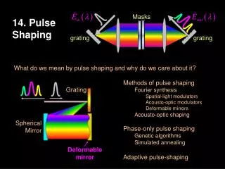
Half-wave plate Dazzler Laser layout: time pulse shaper To obtain the desired square profile a manipulation of the spectral phase and/or amplitude has to be applied. The most popular techniques are the AODPF and the SLM in 4f configuration. We tested the AOPDF and experiment with SLM is going to start. For more details see talk by Cialdi in phin parallel session Care Meeting, LNF Nov 15 2006
Laser layout: CPA Care Meeting, LNF Nov 15 2006
BLUE Filter IR UV BBO1 BBO2 λ/2 Laser layout: THG The third harmonic generator consists of by two type-I BBO crystals, of 0.5 and 0.3 mm thickness. The overall efficiency is about 10% and the energy jitter is 5% rms Care Meeting, LNF Nov 15 2006
Laser layout: UV stretcher The UV stretcher consists of a pair of parallel gratings. It introduces a negative GVD proportional to d, and allows output pulse lengths between 2 and 20 ps. Efficiency of the UV grating is about 65%, the overall energy losses are more than 80% Care Meeting, LNF Nov 15 2006
Laser system layout: spectral and time diagnostics • Diagnostics routinely used to monitor time/spectral features of SPARC laser : • Ir+ blue commercial spectrometers resolution > 0.3 mn • ps resolution streak camera • UV home-built spectrometer with 0.05 nm resolution 10 mn bandwidth • UV home-built multi-shot cross-correlator resolution (IR pulse FWHM) Care Meeting, LNF Nov 15 2006
UV spectral-temporal measurements When a large linear chirp α is applied, as in UV stretcher, the spectral profile at 266 nm gives a direct reconstruction of the intensity profile in time See talk by Petrarca in Phin parallel session • The UV spectrometer can be used as a single-shot time profile diagnostics. • To produce a flat time profile a square-like spectrum is required Care Meeting, LNF Nov 15 2006
Optical transfer line to the cathode • The optical transfer line transports the laser beam to the cathode 10 m away. The laser impinge on the cathode from a mirror in vacuum at normal incidence • The transverse profile is selected by an iris and then imaged on the cathode. • Good pointing stability has been observed (~50 μm). Care Meeting, LNF Nov 15 2006
Motivations Laser phase stability is mandatory for stable machine operation. For SPARC phase 1 is requires < 2ps rms, other application demands for more challenging level of synchronization. Coherent Synchrolock Care Meeting, LNF Nov 15 2006
Laser to RF phase-noise measurements Care Meeting, LNF Nov 15 2006
Phase noise at oscillator level Statistics on the laser to RF Relative phase Stdev=0.34 ps FFT of the relative phase Care Meeting, LNF Nov 15 2006
High energy UV @ 10 Hz 2856 MHz cavity RF to Laser synchronization: measurements on 10 Hz UV pulses On time scale of 30 minutes the phase jitter is within σRMS=0.47 ps. Investigation of the causes of the slow drift (temperature?) and active RF phase shift compensation. Care Meeting, LNF Nov 15 2006
Dazzler experience The dazzler was studied as a stand-alone system at politecnico in Milan. The shaped profile was imposed by producing a square spectrum and add even terms polynomial phase. The distortion introduced by the amplification and the THG has been investigated in collaboration with LCLS and SDL at Brookhaven Nat. Lab. Time distribution at oscillator level Time distribution after the UV conversion C. Vicario et al, EPAC04 H. Loos et al, PAC05 Care Meeting, LNF Nov 15 2006
0.1 0.5 1 DAZZLER experience at SPARC: amplified IR short pulse The UV spectral shape as function of the input IR pulse length Measured (solid) and simulated (dots) harmonics spectra IR pulse length [ps] C. Vicario et al, Opt. Lett, 31,2006, 2885 A large enough pulse width (≥0.6 ps) is needed to preserve the square spectrum throughout the third harmonic generation
The UV temporal and spectral profile • Using a chirped IR pulse (with 0.5 ps duration) and a square-like infrared spectral intensity we obtained a square-like UV shape. • The measured UV rise time appears to be too long, 2.5-3 ps. Care Meeting, LNF Nov 15 2006
Modified UV stretcher to obtain sharper rise time Care Meeting, LNF Nov 15 2006
Preliminary measurements: UV time and spectral intensity UV cross-correlation with 0.5 ps IR probe UV spectrum converted in time (blue) The rise time is 1.5 ps Calculated cross-correlation between the measured IR pulse length and the UV (red) Care Meeting, LNF Nov 15 2006
Modified stretcher: considerations • The spectral measurements indicate rise time of less than 1.5 ps can be obtained. New diagnostics is required to measure such feature directly in time. • From simulations, assuming the actual UV bandwidth (1.2 nm) rise time of 1.2 ps is the best result achievable. • The energy losses due to the filtering is about 20%. • To mitigate distortions and aberrations on the transverse laser profile longer focal lengths is advisable. Care Meeting, LNF Nov 15 2006
Conclusive remarks • Synchronization level is satisfying but feedback to compensate the long term drift should be implemented. • Uniform transverse laser intensity is critical for e-beam quality. • Pulse shaping researchs is still facing the rise time problem. The modified UV stretcher can be used to produce sharper pulse edges. • Systematic measurements on the e-beam generated using the flat top laser profile are going on. Care Meeting, LNF Nov 15 2006
Care publications 2006 Published Articles • High-power third-harmonic flat pulse laser generation, S. Cialdi, M. Petrarca, C. Vicario, Opt. Lett.,31, 2885 (2006) and Virt. J. of Ultrafast Scie. (2006). • Rectangular pulse formation in a laser harmonic generation, S.Cialdi, F. Castelli, I. Boscolo, Appl. Phys. B 82, 3 (2006) 383-389 • A train of micro-bunches for PWFA experiments produced by RF photoinjectors,. M. Boscolo, M. Ferrario, C. Vaccarezza, I. Boscolo, F. Castelli, S. Cialdi. Int. J. Mod. Phys. B (2006) Care Meeting, LNF Nov 15 2006
Care publications 2006 Proceedings and reports • M. Boscolo, M. Ferrario, C. Vaccarezza, I. Boscolo, F. Castelli, S. Cialdi, “Laser comb: simulations of pre-modulated e beams at the photocathode of a high brightness rf photoinjector, Edimburgh, EPAC 2006 • M. Petrarca, P. Musumeci, M. C. Mattioli, C. Vicario, G. Gatti, A. Ghigo, Production of Temporally fla-top UV laser pulses for SPARC photoinjector, Proc. of EPAC 2006, Edinburgh, Scotland, THPCH153 • C. Vicario , M. Bellaveglia, D. Filippetto, A. Gallo, G. Gatti, A. Ghigo, P. Musumeci, M. Petrarca, Commissioning of the laser system for SPARC photoinjector Proc. of EPAC 2006, Edinburgh, Scotland, THPCH151 Physics degree thesis • Compressione di un impulso laser Nd:YAG con fibra in un sistema 4f-asimmetrico, Valeria Brizzolara, 27/Ott/2006 Care Meeting, LNF Nov 15 2006