Download
1 / 29
290 likes | 479 Views
Lecture 2: RF Issues for Software Radios RF Engineering for the DSP Engineer. TOPICS RF Receiver Chain RF Transmitter Chain A Quantitative perspective of noise and distortion Overcoming RF limitations with DSP. What You’ll Learn. Role of RF in SDR SDR RF Structures

E N D
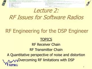
Lecture 2:RF Issues for Software RadiosRF Engineering for the DSP Engineer TOPICS RF Receiver Chain RF Transmitter Chain A Quantitative perspective of noise and distortion Overcoming RF limitations with DSP
What You’ll Learn • Role of RF in SDR • SDR RF Structures • Common Performance Metrics • SDR Amplifiers and Overcoming RF Problems with DSP • Impact of MEMs
Role of RF in SDR • Why are we focusing first on Hardware for a Software radio? • Radio may be defined digitally, but the real world is analog.
Generic Transmitter Antenna Digital Input Digital to Selection and Conversion Analog Amplification Conversion transmitter section
Generic Receiver Antenna Digital Output Analog - to - Selection Conversion Digital Conversion RF Front End
Purpose for the RF • Extract a desired low level signal: 10-16 to 10-3 Watts. • Reject out of band noise and interference • Convert signal’s center frequency to a range compatible with the A/D. • Modulate, amplify, and filter signal for transmission. • Minimize additive noise and distortion
Goals of RF in SDR (1/3) • Support MBMMR – Multi-band, multimode radio • Operate over numerous bandwidths, frequencies, waveforms • Implies wideband operation, but… • Produce highest quality signal for baseband processing • Reject out-of-band noise and interference • Implies narrowband operation…
Goals of RF in SDR (2/3) • Facilitate recovery of weak signals in presence of strong interferers • Wide Dynamic Range • Implies High Quality Components (Means high cost) • Practical Considerations • Low Cost • Low Power • Small Form Factors
Goals of RF in SDR (3/3) • Have your cake and eat it too… • However, complementing hardware with software changes the RF “cake” equation
RF View of Radio Systems (1) • Antenna Design • Receiver Design • Topology of Receivers • Component Issues • Special capabilities • Transmitter Design • Topology of Transmitters • Component Issues • Special capabilities
RF View of Radio System (2) • Noise and Distortion Characterization • Noise • Non-linear distortion • Compensation for distortion • Power Supply and Consumption Considerations
Key Antenna Issues • Most antennas support bandwidths on the order of 10% of the carrier frequency, • Multimode radios 900 MHz to 2 GHz are difficult to support with the same antenna • Impendence, hence matching can vary with the environment • Form factor is important for handsets
Key Antenna Design Issues (2) • Gain versus directionality trade-off • Sensitivity to coverings (e.g., hand) • Diversity design -- multiple antennas and smart antenna algorithms • Radiating head
Key Receiver Parameters • Sensitivity: • Defines the weakest signal that a receiver can detect and is usually determined by the various noise sources in the receiving system. • Selectivity: • The ability of the receiver to detect the desired signal and reject others. • Spurious Response: • The spurious response is a receiver’s freedom from interference due to these internally generated signals or their interaction with external signals. • Stability: • Receiver gain & frequency change with temperature, time, voltage, etc.
Characteristics that Determine Suitability of Receiver Topologies (2) • Dynamic Range: The difference in power between the weakest signal that the receiver can detect and the strongest signal that can be supported (either in band or out of band) by the receiver without detrimental effects
Dynamic Range Constraints Spurious Signal Limited Noise Limited Bit Error Rate (BER) Usable Dynamic Range Received Signal Power
Factors Impacting Dynamic Range A/D Converter Constraints Range Selected Dynamic Range AGC and Power Control Analog Front End Constrains
Various Types of Receivers- Tuned Radio Frequency Receiver Input signal level may span 100 dB in dynamic range To A/D Converter LNA BPF AGC RX filter Not very practical
Tuned Radio Frequency Receiver Disadvantages • Not as practical • Extreme demands on RF and A/D • Tunable very narrowband filters • Dynamic range of LNA • Advantages • Few analog components • Isolation problems minimized
Direct Conversion Receiver I Input signal level may span 100 dB in dynamic range LNA BPF BPF AGC LO ADC 90o RX filter RX filter Q • Advantages • Fewer parts • Analog Images Eliminated • Conceptually simple • Possibly lower power consumption • Disadvantages • High isolation needed in mixer between LO and LNA input • eg, signal = -116 dBm, LO = 5dBm, thus isolation >> 120 dB • Phase noise of LO critical • DC offset at A/D substantial and dynamic • Balanced mixers needed • Second order distortions occur in band
Direct Conversion Transmitter Architecture Spurs typically 60 dB down or more I Binary Data Source Frequency Source (DDS or Programmable VCO) Power Amplifier BPF BPF Q I/Q LO source RF VCO • Advantage • Conceptually simple filter requirements • Low complexity • Circumvents image problems • Disadvantage • Not as practical because of isolation problems • Balance in I&Q • Consistent performance over wide band
Multiple Conversion Receiver I LNA BPF BPF LO BPF AGC BPF 90o Image filter Image filter RX filter Q IF LO IF LO • Advantages • More isolation than direct conversion or single conversion (due to distributing gain into to sections) • Better rejection of ACI • Better gain possible through distributed amplificaiton • Disadvantages • More parts • More power consumption? Multiple conversion possible, but not as common
IF and Low -IF Conversion Receiver I ADC LNA BPF LO BPF AGC BPF 90o Image filter RX filter Q IF LO • Advantages • More isolation than direct conversion – less DC offset • Lower parts count than dual conversion Analog Digital • Disadvantages • Gain is limited • More image rejection required over direct conversion
Review of the Mixing Process Amplitude Desired signal Adjacent channel interference - 136MHz 136MHz -d -1 1 d Amplitude Desired signal downconverted Adjacent channel interference upconverted by the mixer Desired signal corrupted by interference - -1-68=-wd+68 1+68=wd-68 -d-68 -1+68 1-68 d+68
Two Stage Transmitter BPF Power Amplifier I Binary Data Source Frequency Source (DDS or programmable VCO) BPF BPF Q RF VCO RF VCO • Advantage • Better isolation • Disadvantages • More parts and higher cost • Higher power consumption
Transmitter Component Issues (1/2) • Transmit IF VCO • Phase Noise Provides Significant Modulation to Narrowband Signals • Up-Converter • Linearity to Reduce Spurious Products • Modulator • Balance Between I&Q Required to Keep Distortion (Sidebands) Down • Variable Gain Amplifier • Linearity and Fidelity
Transmitter Component Issues (2/2) • Transmit Filters • Must Prevent PA Transmitter Noise Leakage (supplement duplexer) • Low Loss required • Power Amplifiers • Cost - especially for base stations • Spurious response (source of interference) • Packing to handle heat • Low distortion traded for power efficiency traded for bandwidth (in practice only about 25% of the battery is effectively used during the talk time
Key Receiver Component Issues (1/2) • Duplexers • full duplex, e.g., AMPS is difficult and expensive • half duplex, e.g., GSM still some difficulty in integration • duplexers that work both for TDMA and FDMA • Low noise amplifier (LNA) • trade off in gain, noise, power consumption, and dynamic range (noise figure is ratio of output SNR to input SNR) • low power consumption needed
Key Receiver Component Issues (2/2) • RX filter • Initial BPF after antenna • rejects out of band interference • helps isolate of the tx and rx • Image Reject BPF before mixer • protects mixer from interference • suppresses spurious signals generated by mixer impacting LNA • RF Mixer • Spurious response • LO drive level • too high -- power consumption issue • too low -- more harmonic distortion • Isolation between RF, IF, and LO ports limits post mixing harmonics • Harmonics due to mixer and LNA non-linearities may end up in the IF pass band after mixing