Download
1 / 40
400 likes | 545 Views
Update on JLab MEIC Project. Vasiliy Morozov for JLab’s MEIC Study Group EIC Generic Detector R&D Advisory Committee Meeting, BNL, January 13, 2014. Outline. Introduction MEIC project overview Accelerator design Luminosity Polarization Detector Concept Machine integration Performance

E N D
Update on JLab MEIC Project Vasiliy Morozov for JLab’s MEIC Study Group EIC Generic Detector R&D Advisory Committee Meeting, BNL, January 13, 2014
Outline • Introduction • MEIC project overview • Accelerator design • Luminosity • Polarization • Detector • Concept • Machine integration • Performance • Backgrounds • Summary
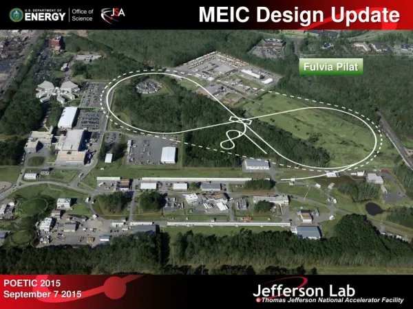
EIC at JLab e injection Hall D MEIC Ion linac Pre-booster IP2 C E B A F IP1 High-Energy Arc (Stage II) Halls A-C • Stage I MEIC • CEBAF as full-energy e-/e+ injector • 3-12 GeV e-/e+ • 25-100 GeV protons • 12-40 GeV/u ions • Stage II EIC • up to 20 GeV e-/e+ • up to 250 GeV protons • up to 100 GeV/u ions • Two independent but complementary detectors
MEIC Layout Prebooster Electron cooling Ion source Warm large booster (up to 25 GeV/c) Three Figure-8 rings stacked vertically SRF linac Cold 25-100 GeV/c proton collider ring Warm 3-12 GeV electron collider ring Medium-energy IPs with horizontal beam crossing Injector 12 GeV CEBAF Cross sections of tunnels for MEIC
MEIC Design Features CEBAF as a full-energy electron/positron injector Luminosity Multi-stage DC and ERL-based conventional electron cooling: small-emittance ion bunches Beam parameter choice: short low-charge bunches at a high repetition rate Interaction region design: small beam size at IP, crab crossing Ion polarization stability and ease of manipulation All ion species including deuterons Figure-8 ion booster and collider ring design Novel detector concept Full acceptance Far-forward hadron detection Technical design limited to conventional technology as much as possible Electron current <3 A, proton/ion current <0.5 A Synchrotron radiation <20 kW/m Warm magnets <1.7 T Cold magnets <6 T
MEIC Design Report Table of Contents Executive Summary Introduction Nuclear Physics with MEIC Baseline Design and Luminosity Concept Electron Complex Ion Complex Electron Cooling Interaction Regions Outlook arXiv:1209.0757
Design Parameters for Full-Acceptance Detector * Including space-charge effects and assuming conventional electron cooling
Electron Cooling in MEIC Use conventional electron cooling mechanism Multi-stage cooling scenario Prebooster: standard DC electron cooling for beam accumulation from positive source Collider ring: bunched high-energy electron cooling after injection (initial), after acceleration and re-bunching (final), and during collisions (continuous) Magnetized injector of high-charge short electron bunches (a similar injector operates at BINP) Energy recovery linac to reduce power consumption Ultra-fast (beam-beam or RF) kicker Compact circulator ring to reduce electron source current Cooling Cooling SRF linac to high-energy collider ring Ion source Prebooster (accumulator ring) Medium-energy collider ring Large booster solenoid ion bunch electron bunch Cooling section Fast kicker Fast kicker circulator ring energy recovery dump injector SRF Linac
Lattice design of geometrically-matched collider rings is completed Detector locations minimize synchrotron and hadronic backgrounds Close to arc where ions exit Far from arc where electrons exit Collider Rings IPs IP ions e- ions e-
Nonlinear Beam Dynamics Tight beam focusing (small *) at IP causes momentum-dependence of particle oscillation frequencies, i.e. chromaticity d/(dp/p) Each interaction region contributes x,y of ~130 in the ion ring and ~50 in the electron ring Chromatic betatron tune spread may cause particle loss due to resonances Chromatic beam smear at IP may increase beam size and reduce luminosity Chromaticity compensation scheme Local chromaticity compensation: dedicated insertions cancel chromatic effects in each IR Insertion design utilizes dynamical and magnetic field symmetries for optimal performance Simultaneous compensation of chromatic betatron tune spread and beam smear at IP The concept has been successfully demonstrated, example of chromaticity compensation using only two sextupole families: Ions Electrons 5 p/p 5 p/p p/p = 0.710-3 at 5 GeV/c p/p = 0.310-3 at 60 GeV/c
Ion Polarization Design requirements High polarization (>70%) of protons and light ions (d, 3He++, and possibly 6Li+++) Both longitudinal and transverse polarization orientations available at all IPs Spin flipping (can be done e.g. at the source) Figure-8 ring as a solution No preferred periodic spin direction, energy-independent zero spin tune Polarization can be controlled by small magnetic fields Eliminates depolarization problem during acceleration Works for all ion species including deuterons Acceleration and spin matching Polarization is stabilized by weak (<3 Tm) solenoids in all ion rings Injection and extraction from straight with solenoid Polarization control in the collider ring Beam is injected longitudinally polarized, accelerated and then the desired spin orientation is adjusted Weak solenoids for deuterons (<1.5 Tm each) Weak radial-field dipoles for protons (<0.25 Tm each) Small or no orbit excursions, easy magnet field ramp Prebooster Large Booster Collider
Electron Polarization with Continuous Injection Design requirements High polarization (>70%) and sufficiently long life time Longitudinal polarization at all interaction points Spin flipping (can be done e.g. at the source) Electron polarization scheme Fully-polarized electron beam is injected from CEBAF Polarization is vertical in the arcs to avoid spin diffusion Universal spin rotators turn polarization from vertical to longitudinal and back in straights Spin matching to extend polarization lifetime Continuous injection to maintain high polarization at high energies spin arc dipole Solenoid 1 arc dipole Solenoid 2 e- φ1 α1≈8.8º spin φ2 α2≈4.4º Lost or Extracted P0 (>Pt) Pt
Full-Acceptance Detector Concept 50 mrad crossing angle Improved detection, no parasitic collisions, fast beam separation Forward hadron detection in three stages Endcap with 50 mrad crossing angle Small dipole covering angles up to a few degrees Far forward, up to one degree, for particles passing the accelerator quads Low-Q2 tagger Small-angle electron detection
Detector Modeling & Machine Integration Fully-integrated detector and interaction region satisfying Detector requirements: full acceptance and high resolution Beam dynamics requirements: consistent with non-linear dynamics requirements Geometric constraints: matched collider ring footprints small angle hadron detection IP FP (from GEANT4) far forward hadron detection n, g low-Q2 electron detection ion quads large-aperture electron quads ~60 mrad bend p small-diameter electron quads e 50 mrad beam (crab) crossing angle p Fixed trackers in vacuum? Thin exit windows Roman pots central detector with endcaps dual-solenoid in common cryostat 4 m coil 1 m Ion quadrupoles RICH + TORCH? 1 m Endcap barrel DIRC + TOF 2 Tm dipole Electron quadrupoles e/π threshold Cherenkov EM calorimeter Tracking EM calorimeter Trackers and “donut” calorimeter EM calorimeter
Central Detector Two independently designed but complementary central detectors No need for beam sharing in a ring-ring collider Novel iron-free dual solenoid for one of the detectors Improved endcap acceptance Efficient fringe-field compensation Easily accessible and light weight dual-solenoid in common cryostat 4 m coil RICH + TORCH? Coil wall Coil wall EM calorimeter e/π threshold Cherenkov EM calorimeter barrel DIRC + TOF forward tracker forward tracker Si-pixel vertex + disks 3 m central tracker 1 m deep 2 m deep EM calorimeter (top view) 3 m 5 m First TOSCA model of 3T dual solenoid (inspired by ILC 4th concept detector)
Forward Hadron Detection Large crossing angle (50 mrad) Moves spot of poor resolution along solenoid axis into the periphery Minimizes shadow from electron FFQs Dipole before quadrupoles Further improves resolution in the few-degree range Low-gradient quadrupoles Allow large apertures for detection of all ion fragments 7 m from IP to first ion quad Ion quadrupoles: gradient, peak field, length 36 T/m, 7.0 T, 1.2 m 51 T/m, 9.0 T, 2.4 m 89 T/m, 9.0 T, 1.2 m 1 m 1 m Endcap detectors 2 T dipole Permanent magnets e Electron quadrupoles 2 x 15 T/m 34 T/m 46 T/m 38 T/m Tracking Calorimetry 5 T, 4 m dipole Crossing angle
Far-Forward Hadron Detection Good acceptance for ion fragments Large downstream magnet apertures/ small downstream magnet gradients Good acceptance for low-pT recoil baryons Small beam size at second focus Large dispersion Good momentum and angular resolution Large dispersion No contribution from D to angular spread at IP Long instrumented magnet-free drift space Sufficient separation between the beam lines (n, γ) ZDC Aperture-free drift space 20 Tm dipole (in) 2 Tm dipole (out) p solenoid e S-shaped dipole configuration optimizes acceptance for neutrals Thin exit windows Roman pots at focal point 50 mrad crossing angle Asymmetric IR (minimizes chromaticity) x Ions βFP < 1 m βx* = 10-20 cm DFP ~ 1 m βy* = 2 cm D* = D'* = 0 FP IP
Far-Forward Acceptance for Charged Fragments (protons rich fragments) (neutron rich fragments) Δp/p = -0.5 Δp/p = 0.0 Δp/p = 0.5 (spectator protons from deuterium) (exclusive / diffractive recoil protons) (tritons from N=Z nuclei)
Far-Forward Acceptance Transmission of particles with initial angular and p/p spread vs peak field Quad apertures = B max / (fixed field gradient @ 100 GeV/c) Uniform particle distribution of 0.7 in p/p and 1 in horizontal angle originating at IP Transmitted particles are indicated in blue (the box outlines acceptance of interest) 9 T max 6 T max 12 T max electron beam
Far-Forward Acceptance for Neutrals Transmission of neutrals with initial x and y angular spread vs peak field Quad apertures = B max / (fixed field gradient @ 100 GeV/c) Uniform neutral particle distribution of 1 in x and y angles around proton beam at IP Transmitted particles are indicated in blue (the circle outlines 0.5 cone) 9 T max 6 T max 12 T max electron beam
Momentum & Angular Resolution Protons with p/p spread are launched at different angles to nominal trajectory Resulting deflection is observed at the second focal point Particles with large deflections can be detected closer to the dipole |p/p| > 0.005 @ x,y = 0 electron beam ±10 @ 60 GeV/c
Far-Forward Detection Summary • Neutrals detected in a 25 mrad (total) cone down to zero degrees • Space for large (> 1 m diameter) Hcal + Emcal • Excellent acceptance for all ion fragments • Recoil baryon acceptance: • up to 99.5% of beam energy for all angles • down to at least 2-3 mrad for all momenta • full acceptance for x > 0.005 • Resolution limited only by beam • longitudinal p/p ~ 310-4 • angular ~ 0.2 mrad n, γ 20 Tm dipole p 2 Tm dipole solenoid e • 15 MeV/c resolution for 50GeV/u tagged detueron beam
Detector Background Synchrotron radiation background Suppressing SR in the detector Detector solenoid is aligned with the electron beam Detector is placed far from electron arc exit Soft last bend Working on SR background calculations with a consultant, M. Sullivan, from SLAC SR from the last bend does not seem to be an issue Preliminary conclusion is that overall SR background is under control Hadronic background Dominated by interaction of beam ions with residual gas upstream of IP Suppressing hadronic background Detector is placed close to ion arc exit Simple estimate by scaling from HERA gives ~10 times lower hadronic background s of 4,000 at MEIC and of 100,000 at HERA Same ion current and vacuum Upstream straight distance ratio: 50 m / 120 m = 0.4 Average hadron multiplicity: (4000/100000)1/4 = 0.4 p-p cross section (fixed target): σ(90 GeV)/σ(920 GeV) = 0.7
Summary First MEIC design completed and comprehensive design report released Emphasis on luminosity Multi-stage electron cooling Beam parameter choice Interaction region design Emphasis on polarization Figure-8 ring design Polarized light ions including deuterons Electron polarization maintained by continuous injection Fully-integrated detector and interaction region design completed Detector features full acceptance and high resolution Excellent detection of recoil baryons, spectators, and target fragments Optimized for minimizing detector background Consistent with non-linear dynamics requirements Matched beam line footprints Many studies still in progress Optimization and comprehensive simulation of the detector region and background Optimization of the non-linear dynamics Design of the second detector
Announcement EIC14 The International Workshop for Accelerator science and Technology for Electron-ion Collider Including a dedication session on Detector Design, Integration and Backgrounds March 17 – 21, 2014 Newport News, Virginia, USA Welcome to Virginia!
MEIC Design Goals Energy Natural continuation of 12 GeV CEBAF program bridging the gap to HERA/LHeC Full coverage of s from a few 100 to a few 1000 GeV2 Electrons 3-12 GeV, protons 25-100 GeV, ions 12-40 GeV/u Ion species Polarized light ions: p, d, 3He, and possibly Li Unpolarized light to heavy ions up to A above 200 (Au, Pb) Up to 2 individually designed detectors Luminosity About 1034 cm-2s-1 per interaction point Maximum luminosity should optimally be around √s=45 GeV Polarization At IP: longitudinal for both beams, also transverse for ions only All polarizations >70% desirable Upgradeable to higher energies and luminosity 20 GeV electrons, 250 GeV protons, and 100 GeV/u ions
Electron Source for Electron Cooling • MEIC high-energy electron cooling requires a source of ~2 nC few-cm long electron bunches with a repetition rate of ~15 MHz and an average current of ~30 mA. • Slava suggested using a short-pulse high-bunch-charge high-repetition-rate magnetized DC gun with subsequent bunch compression. • Such a scheme, with the exception of beam magnetization, seem to exist at BINP and has been used as an electron source for NovoFEL since 2003. • A DC gun with a thermionic metal-oxide gridded cathode has the following parameters: • All gun (and injector) parameters seem consistent with the electron cooler requirements. • A thermionic RF gun is being developed at BINP to replace the DC gun. The reasons for upgrade are not clear but, perhaps, involve improved cathode lifetime and higher current. • Beam tests of the RF gun started recently with encouraging results.
Crab Crossing Effective head-on bunch collisions restored with 50 mrad crossing angle Luminosity preserved Two feasible technologies Dispersive crabbing using regular accelerating/bunching cavities in dispersive region Deflective crabbing using transverse electric field of SRF cavities (developed at ODU) Outgoing At IP Incoming
Continuous Injection Scheme Magnet Field • During the injection time: kickers on. Septum Magnet X0 • Kickers on during the first few turns (~9-15 μs). The injected beam won’t be close to the Septum Magnets (physically) due to the betatron tune. Magnet Field Septum Magnet X2 X1 • Kickers off after a few turns (~9-5μs). The injected beam will dampen to the closed orbit after a few horizontal damping times. Magnet Field Septum Magnet
Continuous Injection Bunch Pattern • I : micro bunch trains from CEBAF in 4.7μs (one revolution time of MEIC electron ring), providing a 2.4mA averaged beam current. 4.7μs (1 turn), Iave1=2.4mA • II : macro bunch trains in 1 second, providing 1.2μA averaged beam current. Iave3 Iave2 Iave1 <ps (<1mm) 3.192pC duty factor 7.5e-4 1.33ns (40cm) 748.5MHz • III: macro bunch trains every one minute, providing 20nA averaged beam current. I duty factor 0.0167 60s duty factor 5e-4 9.4ms, 2000 turn …… …… …… • Bunch pattern: I II III • Comments • The peak current in I can be reduced by more turns injection (Iave1 keeps constant). But this may disturb the injected beams due to the septum field with kickers on. Two to three turns injection is acceptable. • The Iave2 can be increased by reducing the time interval between the macro bunches in II. While this leaves less time for injected beams to damp and may interference with the new injected beams. • The Iave3 can be increased by increasing Iave1 and Iave2 or reducing the time interval in III. While this will reduce the experimental time. t t=Trev t 1s, Iave2=1.2μA Iave3=20nA II III
Beam Synchronization & Collision Pattern Path length difference in collider rings Electrons travel at the speed of light, protons/ions are slower Slower proton/ion bunches may not meet electron bunch again at IPafter one revolution Synchronization must be achieved at every IP in the collider rings simultaneously Conceptual solution Varying number of bunches (harmonic number) in the ion collider ring would synchronize beams at IPs for a set of ion energies (harmonic energies) To cover the energies between the harmonic values varying electron orbit length up to half bunch spacing varying RF frequency (less than 0.01%) CEBAF RF frequency fixed, dynamic adjustment of electron bunch spacing at injection Collision pattern at IP Each time an ion bunch returns to IP, it will collide with a different electron bunch (it may collide with all or a subset of electron bunches) * Number of electron bunches is 3370 ** Assuming the same electron and ion orbit lengths (1350 m) at 100 GeV proton energy
Small-Angle Electron Detection Low-Q2 tagger Dipole chicane for high-resolution detection of low-Q2 electrons e- x e- ions (top view) ions low-Q2 tagger Electron beam aligned with solenoid axis e- final focusing elements
Far-Forward Angular Acceptance Quad apertures = 9, 9, 7 T / (By /x @ 100 GeV/c), dipole aperture = -30/+50 40 cm Uniform distribution of 1 in x and y angles around proton beam at IP for a set of p/p The circle indicates neutrals’ cone electron beam electron beam p/p = 0.5 p/p = -0.5 neutrons p/p = 0
Momentum & Angular Resolution Protons with different p/p launched with x spread around nominal trajectory Resulting deflection is observed 12 m downstream of the dipole Particles with large deflections can be detected closer to the dipole |x| > 3 mrad @ p/p = 0 ±10 @ 60 GeV/c electron beam electron beam
Initial SR Background Calculations Synchrotron radiation photons incident on various surfaces from the last 4 electron quads 38 P+ 8.5x10⁵ 2.5W 4.6x10⁴ 240 2 e- 3080 Rate per bunch incident on the surface > 10 keV Beam current = 2.32 A 2.9x10¹⁰ particles/bunch X Rate per bunch incident on the detector beam pipe, assuming 1% reflection coefficient and 4.4% solid angle acceptance M. Sullivan July 20, 2010 F$JLAB_E_3_5M_1A Z Electron energy = 11 GeV x/y = 1.0/0.2 nm-rad M. Sullivan’s talk at the 2nd Detector/IR Mini-workshop
Immediate Outlook & R&D • Electron cooling • Electron cooling of medium energy ion beam (by simulations) • ERL circulator cooler design optimization, technology development • ERL-circulator cooler demo (using JLab FEL facility) • Interaction region • Detector integration • Sufficient dynamic aperture with low beta insertions • Polarization • Demonstrate superior ion polarization with figure-8 ring • Electron spin matching • Collective beam effects • (Long time scale) beam-beam with crab crossing • Space charge effects in pre-booster • Electron cloud in the ion rings and mitigation • Ion injector complex optimization and beam studies Bold font indicates high priority