Download
1 / 30
300 likes | 362 Views
MEIC Design Update. Fulvia Pilat. POETIC 2015 September 7 2015. Outline. MEIC baseline Design strategy for high luminosity and polarization

E N D
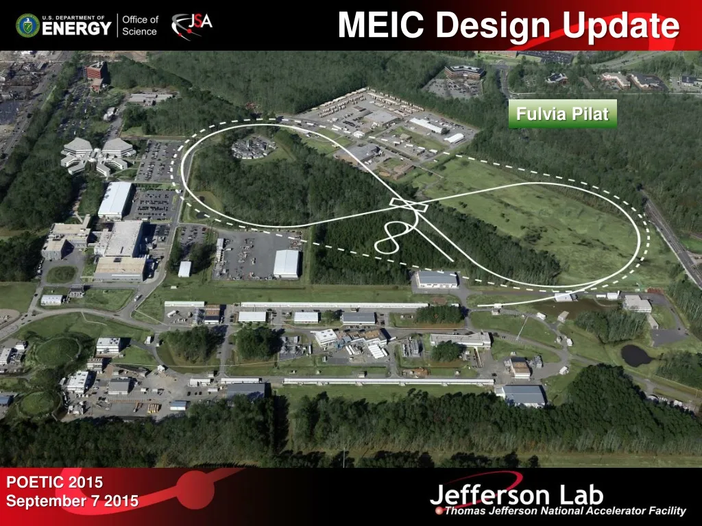
MEIC Design Update Fulvia Pilat POETIC 2015 September 7 2015
Outline MEIC baseline • Design strategy for high luminosity and polarization • 2.1km figure-8 ring-ring collider, e-ring based on PEP-II design and components and CEBAF as full energy injector, new ion complex based on super-ferric magnets • Focus: minimization of technical risk • Design and cost estimate successfully reviewed in January 2015 Present focus • Design optimization for cost reduction and further minimization of technical risk • Development and execution of pre-project R&D program Future plans
MEIC Design Goals • Energy • Full coverage of √s from 15 to65 GeV • Electrons 3-10 GeV, protons 20-100 GeV, ions 12-40 GeV/u • Ion species • Polarized light ions: p, d, 3He, and possibly Li • Un-polarized light to heavy ions up to A above 200 (Au, Pb) • Space for at least 2 detectors • Full acceptance is critical for the primary detector • Luminosity • 1033 to 1034cm-2s-1 per IP in a broad CM energy range • Polarization • At IP: longitudinal for both beams, transverse for ions only • All polarizations >70% • Upgrade to higher energies and luminosity possible • 20 GeV electron, 250 GeV proton, and 100 GeV/uion • Design goals consistent with the White Paper requirements
Design Strategy: High Luminosity and polarization KEK-B already reached above2x1034/cm2/s • The MEIC design concept for high luminosity is based on high bunch repetition rate CW colliding beams All rings are figure-8 critical advantages for both ion and electron beam polarization • Spin precessions in the left & right parts of the ring are exactly cancelled • Net spin precession (spin tune) is zero, thus energy independent • Spin is easily controlled and stabilized by small solenoids or other compact spin rotators • Beam Design • High repetition rate • Low bunch charge • Short bunch length • Small emittance • IR Design • Small β* • Crab crossing • Damping • Synchrotron radiation • Electron cooling
MEIC Baseline Baseline for the cost estimate • Collider ring circumference: ~2100 m • Electron collider ring and lines : PEP-II magnets, RF (476 MHz) and vacuum chambers • Ion collider and booster ring: super-ferric magnets • SRF ion linac • Electron cooling: DC cooler and single-pass ERL, bunched-beam e-cooler Energy range • Electron: 3 to 10 GeV • Proton: 20 to 100 GeV • Lead ions: up to 40 GeV
Baseline Layout Warm Electron Collider Ring (3 to 10 GeV) Booster Linac Booster Ion Source Linac Ion Source CEBAF is a full energy injector. Only minor gun modification is needed MEIC Cost Review December 18 2014
Campus Layout • ~2.1 km circumference • E-ring from PEP-II • Ion-ring with super-ferric magnets • Tunnel consistent • with a 250+ GeV upgrade
MEIC Electron Complex • CEBAF provides up to 12 GeV, high repetition rate and high polarization (>85%) electron beams, no further upgrade needed beyond the 12 GeV CEBAF upgrade. • Electron collider ring design • circumference of 2154.28 m = 2 x 754.84 m arcs + 2 x 322.3 m straights • Meets design requirements • Provides longitudinal electron polarization at IP(s) • incorporates forward electron detection • accommodates up to two detectors • includes non-linear beam dynamics • reuses PEP-II magnets, vacuum chambers and RF • Beam characteristics • 3A beam current at 6.95 GeV • Normalized emittance 1093 mm @ 10 GeV • Synchrotron radiation power density 10kW/m • total power 10 MW @ 10 GeV • CEBAF and the electron collider provide the required electron beams for the EIC. IP Electron Collider Ring Optics Dx(m) x(m), y(m)
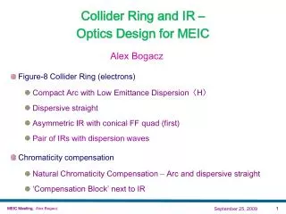
Electron Collider Ring Layout • Circumference of 2154.28 m = 2 x 754.84 m arcs + 2 x 322.3 m straights Figure-8, crossing angle 81.7 Electron collider ring w/ major machine components Spin rotator Spin rotator CCB Tune trombone & Straight FODOs R=155m e- 81.7 Arc, 261.7 Future 2nd IP RF RF Spin rotator Spin rotator IP Forward e- detection
CEBAF - Full Energy Injector • CEBAF fixed target program 5-pass recirculating SRF linac Exciting science program beyond 2025 Can be operated concurrently with the MEIC • CEBAF will provide for MEIC • Up to 12 GeV electron beam • High repetition rate (up to 1497 MHz) • High polarization (>85%) • Good beam quality up to the mA level
Ion Injector Complex Booster (8 GeV) (accumulation) DC e-cooling Ion Sources SRF Linac (285 MeV) • Status of the ion injector complex: • Relies on demonstrated technology for injectors and sources • SRF linac • 8 GeV Boosterto avoid transition for all ion species and based on • super-ferric magnet technology • Injection/extraction lines to/from Booster are designed
Ion Collider Ring disp. supp./ geom. match #3 disp. supp./ geom. match #2 norm.+ SRF Arc, 261.7 tune tromb.+ match elec. cool. R = 155.5 m 81.7 future 2nd IP det. elem. disp. supp. ions beam exp./ match IP disp. supp./ geom. match #3 disp. supp./ geom. match #1 Figure-8 ring with a circumference of 2153.9 m Two 261.7 arcs connected by two straights crossing at 81.7
MEIC Multi-Step Cooling Scheme BB cooler ion sources DC cooler ion linac • DC cooling for emittance reduction • BBC cooling for emittance preservation Booster (0.285 to 8 GeV) collider ring (8 to 100 GeV)
e-p Luminosity 1034 1033 The baseline performance requires a ERL bunched beam cooler but no circulator cooler
Design optimization • Study of lower energy SRF linac, stripping scheme (Collaboration ANL) • DC cooler design (Collaboration Budker institute) • Polarization design and spin tracking • ERL cooler design • Reduction of e- emittance in e- ring • Complete scheme of proton and ion beam formation • Beam synchronization
SRF Linac QWR QWR HWR RFQ 4 cryostats 2 10 cryostats Ion Sources IH 2 cryos 10 cryos 4 cryos MEBT Evaluating to limit the linac energy to ~120 MeV as a cost mitigation option • Linac design based on the ANL linac design. Pulsed linac capably of accelerating multiple charge ion species (H- to Pb67+) • Warm Linac sections (115 MHz) • RFQ (3 m) • MEBT (3 m) • IH structure (9 m) • Cold Linac sections • QWR + QWR (24 + 12 m) 115 MHz • Stripper, chicane (10 m) 115 MHz • HWR section (60 m) 230 MHz
New pulsed SRF ion linac design • QWR and HWR cavity design based on existing design for the ANL Atlas upgrade • Energy reduction from 285 to 100 MeV potential cost reduction by a factor 2-3 • Preliminary evaluation of impacts of lower injection energy to booster is positive, more evaluation in progress
x = 52 cm x = -69 cm Total bending angle and z length are fixed Beam synchronization Issue synchronize energy dependent ion velocity with electrons • Conventional schemes involve magnet movement • Moving magnets in the ion collider ring • Moving whole arcs or a small number of magnets in chicane(s) • With or without harmonic jump • Moving magnets in the electron collider ring & adjusting RF in both rings • Moving (almost) whole arcs or a small number of magnets in chicane(s) • With or without harmonic jump • Some combination of the two schemes Report on MEIC synchronization is to be published in September 2015 All simpler and more practical conventional schemes require harmonic jump asymmetric collision pattern a.k.a. “gear changing” Non conventional schemes (scanning synchronization) do not require orbit change but move slightly the interaction point Example of a chicane design for the ion ring
Gear changing: the good and the bad…. The bad Leads to potential orbit and beam size instabilities (MEIC possible mitigating Factors: strong focusing, Landau damping may dump instabilities) The good • Highly desirable to have each bunch from a ring collide with all other bunches of the other ring for physics measurements • No need to track FOM for each bunch pair as a function of time, each bunch train can be treated as a long macro-bunch thus decoupling the experimental uncertainties from the microstructure of the accelerator • Especially important for polarization measurement in a high repetition accelerator where bunch by bunch measurements are difficult/impossible JLAB in collaboration with Old Dominion University is developing a new code GHOST (GPU‐accelerate High‐Order Symplectic Tracking) to tackle beam-beam and gear-changing effects (development time ~ 2 years)
MEIC R&D Program Pre-project R&D necessary to support a pre-conceptual Design Report (CD0) Total pre-project R&D budget ~5 M$ (EIC NP R&D funds, LDRD, ops redirect, SBIR, VA Commonwealth funds
MEIC super-ferric dipole • 2 X 4m long dipole • NbTi cable • 3 T • Correction sextupole • Common cryostat
Cabling techniques NbTi Rutherford cable NbTi Cable-in-Conduit Pros: Uses mature cable technology (LHC). Semi-rigid cable makes simpler end winding. Semi-rigid round cable can be precisely located. Cryogenics contained within cable. Cons: Ends tricky to support axial forces. Cable requires development and validation. Entire cold mass is a He vessel.
Fabricating CIC conductor for MEIC 1.2 mm 8.4 mm cabling wires onto perforated spring tube cutaway showing foil over-wrap cross-section of fabricated cable cable bent 180° on 2” radius. drawing sheath onto the cable
e-ring RF design • Re-use proven PEP-II RF stations • 476 MHz HOM damped 1-cell cavities • 34 cavities available • 1.2 MW klystrons, 13 available • Including power supplies etc. • Current limited by synch. rad. power at high energy, impedance at low energy nominal Impedance limited Synchrotron power limited 1.2 MW Klystron PEP-II RF cavity 2 MVA HVPS PEP-II Cavities in the SLAC tunnel
ion-ring RF design • 952.6 MHz HOM damped 1-cell cavities, modular JLab type cryomodule • High frequency/high voltage for short bunch (re-bucket at energy) • Double repetition rate for future luminosity upgrade 952.6 MHz single cell 4-seater CM(~4.3m flange to flange) New HOM damped cavity concept
Crab cavity Design by ODU (A. CastillaPh.D project) • 952.6 MHz “RF dipole” like LHC • Modest RF system (no beam loading) • Must have good HOM damping • Count for 1 IP in baseline • Assume cryostat cost/cavity same as ion storage ring
Conclusions and Outlook The MEIC baseline based on a ring-ring design is mature and can deliver luminosity from a few 1033 to a few 1034 and polarization over 70% in the √s15-65 GeV range with low technical risks. We are planning and executing the pre-project R&D (total cost ~5 M$) We continue to optimize the present design for cost and performance. The design can be upgraded in energy and luminosity We are planning to produce a pre-conceptual design in ~2 years
Backup Slides EIC Cost Review - January 26-28, 2015
Performance MEIC baseline Achieved with a single pass ERL cooler For a full acceptance detector For a high(er) luminosity detector
e-ion luminosity For a full acceptance detector For a high(er) luminosity detector