Download
1 / 33
340 likes | 357 Views
Electrical Machines (EELE 4350). Assad Abu-Jasser, PhD Electric Power Engineering site.iugaza.edu.ps /ajasser ajasser@iugaza.edu.ps. Chapter Eight Polyphase Induction Motors. Introduction.

E N D
Assad Abu-Jasser, PhD Electric Power Engineering site.iugaza.edu.ps/ajasser ajasser@iugaza.edu.ps
Chapter Eight Polyphase Induction Motors
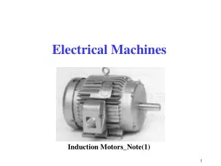
Introduction The rotor of and induction motor receives its power not by conduction as in DC or Synchronous motors rather by induction and therefore called induction motor A winding that receives its power exclusively by induction constitutes a transformer. Therefore, an induction motor is called rotating transformer (rotating secondary winding) An Induction motor is a singly-fed motor. It does not require a commutator, slip-rings, or brushes The absence of brushes eliminates electrical loss due to brush voltage drop and the mechanical loss due to friction between brushes and commutator or slip-rings. Thus it has relatively higher efficiency An induction motor carries alternating current in both stator and rotor windings There are two basic types of induction motors: single-phase and polyphase motors
Construction of Induction MotorStator The outer (stationary) member of an induction motor is called stator and formed by stacking thin-slotted, highly permeable steel laminations These laminations are held together by the stator frame that made of cast iron or mild steel plates and designed to provide mechanical support The slots are intended to house identical coils wound (placed) symmetrically to form balanced polyphase winding
Construction of Induction MotorRotor The rotor is composed of thin-slotted, highly permeable steel laminations that are pressed together onto a shaft with two types Squirrel-cage rotor is used when the load requires little starting torque. The cage is made by molding conducting material (aluminum or copper bars) into the slots. Circular-end rings short circuit the bars in both ends Wound rotor is used when the load requires high starting torque. The rotor has a number of poles equal to that of the stator. These windings are connected to form internal neutral and the other three are connected to three slip rings with 3 brushes riding on them to insert external resistance to get maximum torque at starting
Principle of Operation Φr=1.5Φm
Example 9.1 A 208-V, 60-Hz, 4-pole, three-phase induction motor has a full-load speed of 1755 rpm. Calculate (a) its synchronous speed, (b) the slip, and (c) the rotor frequency The rotor frequency is very small and this is why rotor magnetic loss is usually neglected
Development of an Equivalent Circuit V1=applied voltage R1= stator resistance L1=stator leakage inductance X1=2πfL1=leakage reactance Rr=rotor winding resistance Lb=rotor leakage inductance at s=1 Xb=2πfLb=leakage reactance (s=1) Xr=2πsfLb=sXb=reactance at any s Xm=magnetizing reactance Rc=core resistance N1=stator turns per phase N2=rotor turns per phase Kω1=stator winding factor Kω2=rotor winding factor Φm=maximum phase flux E1=4.44fN1kω1Φm=stator emf Eb=4.44fN2kω2Φm=rotor emf at s=1 Er=sEb=rotor emf at any s Ir=rotor winding current I1=stator (source) current IΦ=Ic+Im=excitation current Ic=core-loss current Im=magnetization current
Example 9.2 A 6-pole, 230-V, 60-Hz, Y-connected, three-phase induction motor has the following parameters on a per-phase basis: R1=0.5 Ω, R2=0.25 Ω, X1=0.75 Ω, X2=0.5 Ω, Xm=100 Ω, and Rc=500 Ω. The friction and windage loss is 150 W. Determine the efficiency of the motor at its rated slip of 2.5%.
An Approximate Equivalent Circuit Well-designed three-phase induction motor has small stator winding resistance to reduce stator copper loss Stator winding leakage reactance is minimized by reducing mean-turn length of each coil Thin laminations of low-loss steel are used to cut down core loss by making core-loss resistance high The permeability of the steel selected for laminationsis high and having low flux density below the knee With the above assumptions, an approximate equivalent circuit is obtained by moving the magnetizing branch directly with the source. This will simplify the analysis with negligible error
Example 9.3 Using the data of Example 9.2 and the approximate equivalent circuit, determine the efficiency of the motor at its rated slip.
Maximum Power Criterion Maximum Power Transfer occurs when the load resistance is equal to the magnitude of standstill impedance of the motor
Example 9.4 A 120-V, 60-Hz, 6-pole, ∆-connected, three-phase induction motor has a stator impedance of 0.1+j0.15 Ω/phase and an equivalent rotor impedance resistance of 0.2+j0.25 Ω/phase at standstill. Find the maximum power developed by the motor and the slip at which it occurs. What is the corresponding value of the torque developed by the motor?
Maximum Torque Criterion Breakdown slip is directly proportional to the rotor resistance but maximum torque developed is independent of the rotor resistance
Example 9.5 Using the data of Example 9.4, determine (a) the breakdown slip, (b) the breakdown torque, and (c) the corresponding power developed by the motor.
Further Approximations Z1=R1+jX1 is neglected When the stator impedance is so small so that it can be neglected in comparison with the rotor impedance at standstill
Example 9.6 A 208-V, 60-Hz, 8-pole, Y-connected, three-phase wound-rotor induction motor has a negligible stator impedance and a rotor impedance of 0.02+j0.08 Ω/phase at standstill. Determine (a) the breakdown slip and the breakdown torque. What is the starting torque developed by the motor? If the starting torque of the motor has to be 80% of the maximum torque, determine the external resistance that must be added in series with the rotor.
Maximum Efficiency Criterion The maximum efficiency occurs when the sum of the stator and the rotor copper losses are equal to the rotational loss
Some Important ConclusionsThe Torque Developed The torque developed is proportional to the slip when the applied voltage and rotor resistance are held constant The torque developed is inversely proportional to the rotor resistance at a given slip with the same voltage The torque developed is directly proportional to the square of the voltage at a definite value of slip and rotor resistance For constant torque operation under fixed voltage, the motor slip is directly proportional to the rotor resistance
Some Important ConclusionsThe Rotor Current The rotor current is directly proportional to the applied voltage as long as the rotor resistance and slip held constant The rotor current varies linearly with the slip when the motor operates at low slip Rotor current varies inversely with the rotor resistance
Some Important ConclusionsThe Motor Efficiency For an ideal induction motor Stator copper loss is negligible The rotational loss is zero The equations show that there is a maximum limit to the efficiency If the motor operates at 60% of its synchronous speed, the maximum theoretically possible efficiency under ideal conditions is 60% Therefore, the higher the speed of operation, the higher the efficiency For a motor operating at 5% slip, it can theoretically have an efficiency of 95%
Example 9.7 A 230-V, 60-Hz, 4-pole, ∆-connected, three-phase induction motor operates at a full-speed of 1710 rpm. The power developed at this speed is 2 hp and the rotor current is 4.5 A. if the supply voltage fluctuates ±10%, determine (a) the torque range and (b) the current range.
Equivalent Circuit ParametersThe Blocked-Rotor Test This test is similar to the short-circuit test of a transformer Rotor is held stationary and stator field winding is connected to variable supply voltage until rated current flows in winding Rotor resistance is small (s=1) under this condition and so is the supply voltage The excitation current is quite small and can be neglected Equivalent circuit is simplified & readings of ammeter, voltmeter, & watt-meters are recorded
Equivalent Circuit ParametersThe No-Load Test This test is similar to the no-load test of a transformer but with friction and windage loss Rated voltage is impressed upon stator winding and the rotor is set free to revolve The rotor speed will be almost equal to the synchronous speed At synchronous speed the slip is nearly zero (s=0) and so rotor impedance is almost infinite Equivalent circuit is simplified & readings of ammeter, voltmeter, & watt-meters are recorded
Example 9.8 The test data on a 208-V, 60-Hz, 4-pole, Y-connected, three-phase induction motor rated at 1710 rpm are as follows: The stator resistance (dc) between any two terminals=2.4 Ω No-Load Test Blocked-Rotor Test Power input 450 W 59.4 W Line current 1.562 A 2.77 A Line voltage 208 V 27 V Friction and windage loss=18 W. Compute the equivalent circuit parameters of the motor
Starting of Induction Motors The rotor resistance R2 at starting is smaller than rated value R2/s and so the starting current is high 4-8 times rated current which is not acceptable Starting torques is 2 to 3.5 times full-load value Current could be reduced if lower voltage is impressed on stator but this will also reduce the torque significantly Starting current can be reduced by increasing rotor resistance and this will increase the starting torque High rotor resistance reduces torque at full load, produces higher loss, and causes lower efficiency
Example 9.9 The impedances of the inner cage and the outer cage rotors of a double-cage, three-phase, 4-pole induction motor are 0.2+j0.8 Ω/phase and 0.6+j0.2 Ω/phase, respectively. Determine the ratio of the torques developed by the two cages (a) at standstill (b) at 2% slip