Download

1 / 22
230 likes | 271 Views
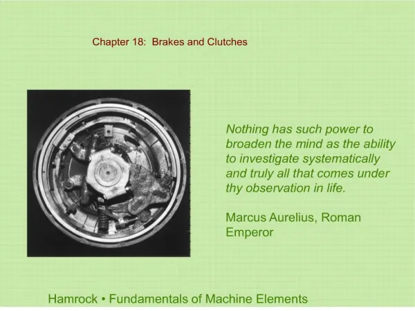
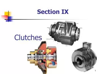
chapter 63. Clutches. FIGURE 63.1 Typical automotive clutch assembly showing all related parts.

E N D
chapter63 Clutches
FIGURE 63.1 Typical automotive clutch assembly showing all related parts.
FIGURE 63.2 (a) When the clutch is in the released position (clutch pedal depressed), the clutch fork is applying a force to the throwout (release) bearing, which pushes on the diaphragm spring, releasing the pressure on the friction disc. (b) When the clutch is in the engaged position (clutch pedal up), the diaphragm spring exerts force on the clutch disc, holding it between the flywheel and the pressure plate.
FIGURE 63.3 The transmission has just been removed. Note that this type of transmission incorporates the bell housing, which was therefore removed at the same time as the transmission. The clutch fork and throwout (release) bearing also came off together. All that remained attached to the engine was the flywheel, clutch disc, and pressure plate.
FIGURE 63.5 A hydraulic clutch linkage uses a master cylinder and a slave cylinder.
FIGURE 63.6 A typical clutch master cylinder and reservoir mounted on the bulkhead on the driver’s side of the vehicle. Brake fluid is used in the hydraulic system to operate the slave cylinder located on the bell housing.
FIGURE 63.7 A racing or high-performance clutch disc lacks the features of a stock clutch disc that help provide smooth engagement.
FIGURE 63.8 A typical stock clutch friction disc that uses coil spring torsional dampers.
FIGURE 63.9 A marcel is a wavy spring that is placed between the two friction surfaces to cushion the clutch engagement.
FIGURE 63.10 Cutaway of the center section of a clutch plate showing the various layers of steel plates used in the construction.
FIGURE 63.11 A coil spring (lever style) clutch pressure plate.
FIGURE 63.12 Typical diaphragm-style pressure plate that uses a Belleville spring.
FIGURE 63.13 A flywheel after it has been machined (ground) to provide the correct surface finish for the replacement clutch disc.
FIGURE 63.14 The starter motor will spin but the engine will not crank if the ring gear on the flywheel is broken.
FIGURE 63.15 A cutaway of a dual-mass flywheel used on a Ford diesel pickup truck.
FIGURE 63.16 (a) Before replacing the clutch, the bell housing should be cleaned and the clutch fork pivot lightly lubricated. (b) The input shaft seal should also be replaced to prevent the possibility of getting transmission lubricant on the friction surfaces of the clutch.
FIGURE 63.17 A transaxle assembly has been removed to replace the clutch. Note the short input shaft. This vehicle did not use a pilot bearing (bushing).
FIGURE 63.18 The clutch pedal linkage moves the clutch fork, which then applies a force against the release bearing, which then releases the clamping force the pressure plate is exerting on the clutch disc.
FIGURE 63.19 The release bearing rubs against the tips of the diaphragm spring.
FIGURE 63.20 The clutch slave cylinder is often corroded because of moisture absorbed by the brake fluid used in the hydraulic clutch. This slave cylinder was disassembled to see if it could be overhauled rather than replaced.
FIGURE 63.21 (a) The replacement hydraulic clutch for a Saturn includes the master cylinder (shown) with the line and the slave cylinder as an assembly. The assembly is even filled with brake fluid! Do not open the master cylinder cap on this unit because Saturn did not provide any method of bleeding air out of the system. (b) The slave cylinder attaches to the bell housing of the transaxle.