Download
1 / 23
280 likes | 771 Views
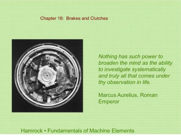
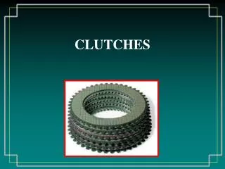
Clutches. Purpose. A clutch is designed with the following requirements Allow the vehicle to come to a stop while the transmission remains in gear Allow the driver to smoothly take off from a dead stop Allow the driver to smoothly change gears

E N D
Purpose • A clutch is designed with the following requirements • Allow the vehicle to come to a stop while the transmission remains in gear • Allow the driver to smoothly take off from a dead stop • Allow the driver to smoothly change gears • Must not slip under heavy loads and full engine power
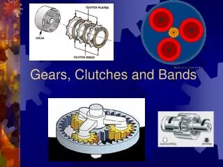
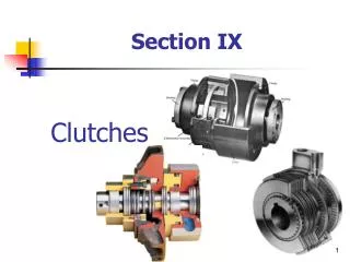
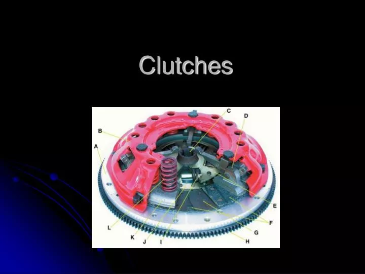
Components • Primary components • Flywheel • Clutch disc • Pressure plate • Throwout bearing • Secondary components • Pilot bearing • Release fork • Slave cylinder How a Clutch Works
Operation • Flywheel • The flywheel attaches to the crankshaft flange • The flywheel’s mass is used to store rotational energy to allow the vehicle to smoothly start out • The flywheel has a machined surface, which the clutch disc rides on • The pressure plate bolts to the flywheel
Operation • Clutch disc • Lined on both sides with a friction lining similar to a brake pad • The internal hub splines to the input shaft of the transmission • The two friction linings are separated by Marcel springs • These springs allow the linings to “slip” on apply and release • The friction linings are connected to the central hub by torsional dampening springs • These springs help dampen the apply and isolate engine/driveline vibration/pulsations
Operation • Pressure Plate • Apply pressure to the clutch disc • “Squeezes” the clutch disc between itself and the flywheel • Allow the clutch disc to release • When vehicle is stopped or driver is shifting • Different designs used • Long • Old Fords, muscle cars, and trucks • Borg and Beck • Chrysler and some early GM • 12 Coil springs • Very stiff pedal • Diaphragm • Most common • Uses a Diaphragm spring
Operation • Throwout Bearing • Exerts force on the pressure plate to compress the springs and release the clutch disc • May be mechanically or hydraulically operated
Operation • Pilot Bushing/Bearing • Located in the rear of the crankshaft • Supports and centers the transmission input shaft • Replace when servicing a clutch
Release Fork Link between the linkage or slave cylinder and the throwout bearing
Release Systems • Mechanical • A system of levers and linkages and/or cables connecting the clutch pedal with the release fork • Hydraulic-Mechanical • A hydraulic master cylinder is used to transmit force to the slave cylinder which pushes on the release fork • Hydraulic • A hydraulic master cylinder is used to transmit force to the slave cylinder which is located in the bellhousing and pushes directly on the throwout bearing
Hydraulic Release How a Clutch Works