Download
1 / 33
380 likes | 613 Views
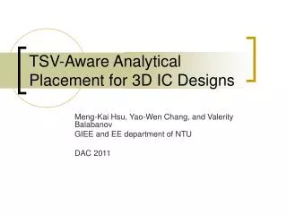
CAD Tools for 3D-IC and TSV-based designs. Kholdoun TORKI Kholdoun.Torki@imag.fr CMP 46, Avenue Félix Viallet, 38031 Grenoble, France http://cmp.imag.fr. Agenda. Introduction Process overview 3D-IC Design Platform 3D-IC industrial CAD tools Conclusion. SiP versus 3D-IC.

E N D
CAD Tools for 3D-IC and TSV-based designs Kholdoun TORKI Kholdoun.Torki@imag.fr CMP 46, Avenue Félix Viallet, 38031 Grenoble, France http://cmp.imag.fr
Agenda • Introduction • Process overview • 3D-IC Design Platform • 3D-IC industrial CAD tools • Conclusion
Tezzaron Process Flow for TSV and DBI (using Via Middle process) Starting wafer in 130nm (5 Cu metal layers + 6th Cu metal as DBI) Source Tezzaron
Resulting 2-tier 3D-IC integration TSV and DBI (Via Middle Process) Bond pad for wire bonding or bump, flip-chip … Top Tier (10um thickness) Bottom Tier (Handle wafer) Source Tezzaron
Interconnections Interconnections in the 3rd dimension at Tezzaron/GF 130nm
Design Methodology The more is the Design Automationon the 3rd dimension, the more is the 3D-IC Integration. 3 D Processor + DRAM + RF + MEMS + Optical communication NoC 2.5 D Multi-Processors + Memory Pixel Sensor (HEP) Simple Imaging Sensor Memory Stack System Complexity 2 D
Tezzaron / GlobalFoundries Design Platform • ModularDesign Platform. It has all features for full-custom design or semi-custom automaticdesign. • PDK : Original PDK from GF + (TSV / DBI) definition from Tezzaron • Libraries : CORE and IO standard libraries from ARM • Memory compilers : SPRAM, DPRAM and ROM from ARM • 3D-IC Utilities : Contributions developments embedded in the platform • Tutorials, User’s setup. • All modules inside the platform refer to a unique variable, making it portable to any site. The installation procedure is straightforward. • Support of CDB and OpenAccess databases.
PDK Tezzaron / GlobalFoundries chrt13lprf_DK009_Rev_1D (Version issued in Q1 2011) assura: FILLDRC LVS QRC assura calibre cds_cdb cds_oa doc eldo hercules hspice prep3DLVS skill spectre strmMaptables_ARM strmMaptables_Encounter calibre: 3DDRC 3DLVS DRC FILLDRC calibreSwitchDef hercules: DRC LVS STAR_RCXT
Collaborative Work on the Design Platform HEP labs contributing with Programs, Libraries, and Utilities. All included in the Design Platform • DBI (direct bonding interface) cells library. (FermiLab) • 3D Pad template compatible with the ARM IO lib. (IPHC) • Preprocessor for 3D LVS / Calibre (NCSU) • Skill program to generate an array of labels (IPHC) • Calibre 3D DRC (Univ. of Bonn) • Dummies filling generator under Assura (CMP) • Basic logic cells and IO pads (FermiLab) • Floor-planning / automatic Place & Route using DBIs, and TSVs (CMP) • Skill program generating automatically sealrings and scribes (FermiLab) • MicroMagic PDK (Tezzaron/NCSU)
Virtuoso Layout Editor with 3D layers and verification Virtuoso from Cadence IC 5.1.41 TSV Back Metal Calibre Back Pad Assura DBI
Customized Menu with some utilities Virtuoso from Cadence IC 6.1.4
Libraries from Providers and Users Univ. Bonn NCSU ARM IPHC FermiLab GF/TSC
Virtuoso / Calibre DRC Interactive Menu Setting switches graphically
Virtuoso / Calibre LVS Interactive Menu Choosing 2D or 3D LVS
3D viewer in Virtuoso Layout - Graphically Interfaced into Virtuoso. - Works for both CDB and OA. - Use a free and open-source VRML viewer.
IPHC Contribution for 3D-IC IO Libraries Pad shell containing TSV and DBI allowing the use of the ARM IO libraries in 3D-IC designs
IPHC Contribution for 3D-IC IO Libraries Pad shell containing TSV and DBI allowing using the ARM IO libraries in 3D-IC designs
IPHC Contribution for 3D-IC IO Libraries Pad shell containing DBI and TSV connecting the pad to the backside bonding pad
3D-IC Automatic P&R using DBI and TSV Design exploration at system level System Level Partitioning 3D Floor-Planning DBI, TSV, IO placement Design exploration at the physical level DBI, TSV, and IO placement & optimization Cells and blocks place & route can be done tier by tier Automatic Place & Route To be done for each tier, then combined for back-annotation to the 3D top level system Extraction, Timing Analysis Physical verification 3D DRC, 3D LVS Similar to the full-custom design flow Dummies Filling Final 3D DRC
Automatic Place & Route with Direct Bond Interface - Custom scripts allowing routing pins on DBIs. - The resulting layout is compliant to the Tezzaron DRC, LVS etc … DBI completely routed down to the lower metal layer DBI array generation + P&R
Automatic P&R with Direct Bond Interface Saving the floor plan for the bottom tier, and apply it for top tier. Place & Route taking into account the locations of the DBIs. The place & route for both tiers is optimal for timing, buffer sizing and power performance. This results in a “correct-by-construction” design.
Custom Scripts Enabling Routing on DBIs Placing logical pins on bumps (DBIs), and extract their location. Before After Generating Physical pins from these locations. They can now be used as terminals for routing. Before After
Automatic P & R Design Flow (From Floor-Plan to Routed Design) - Std cells Placement - Clock Tree Synthesis Filler Cells Placement - DBIs Placement - TSVs Placement - Obstructions on TSVs - Clock routing - Final routing
Cadence is making its 3D-IC design tools available to selected European academic institutions in partnership with the Europractice scheme operated by the UK Science and Technology Facilities Council Rutherford Appleton Laboratory • Proposals are being invited from the existing Europractice/Cadence user base of 378 European academic institutions • These selected early adopters will then be able to more efficiently design 3D-IC systems for their research projects, e.g. in new computer architectures, with the possibility of fabrication via existing broker services offered by CMP (Circuits Multi-Project) in France Source John McLean Rutherford Appleton Laboratory
True 3D Mask Layout Editor Technology Files fully supported by Tezzaron MicroMagic MAX-3D
Conclusion • A Design Platform resulted from the collaboration. • CMC, CMP, MOSIS, FermiLab, Tezzaron, HEP Labs, NCSU • Industrial CAD vendors just starting addressing the features. • Still awaiting for new CAD tools dedicated to 3D-IC Integration : • + 3D-IC Partitioning : both at the system level and the floor-planning level. • + Standard 3D layout editor (i.e. Virtuoso 3D) • + Sign-off tools for 3D-IC Integration : (3D-DRC, 3D-LVS, 3D-Extration)