Download
1 / 14
140 likes | 726 Views
MOS Capacitor Displacement Damage Dose (DDD) Dosimeter. F.R. Palomo 1 , P. Fernández-Martínez 2 , S. Hidalgo 2 , C. Fleta 2 , F. Campabadal 2 , D. Flores 2 1 Departamento de Ingeniería Electrónica , University of Seville 2 Centro Nacional de Microelectrónica (IMB-CNM-CSIC). Outline.

E N D
MOS Capacitor Displacement Damage Dose (DDD) Dosimeter • F.R. Palomo1, P. Fernández-Martínez2 ,S. Hidalgo2, C. Fleta2, F. Campabadal2, D. Flores2 • 1Departamento de IngenieríaElectrónica, University of Seville • 2Centro Nacional de Microelectrónica (IMB-CNM-CSIC)
Outline • Proton Irradiation in MOS Capacitors • HF C-V curves • Radiation Effects in MOS Capacitors • Effect of the Substrate Resistivity • DDD Damage in Sentaurus TCAD • Conclusions: MOS Capacitor DDD Dosimeter
Proton Irradiation on MOS Capacitors • MOS capacitors (substrate resistivity 4.48 Ω·cm) fabricated at the IMB-CNM (CSIC) have been irradiated in the PS facility with 24 GeV protons at CERN HF C-V Characteristic P-type substrate • Drastic reduction of the accumulation capacitance in the irradiated devices
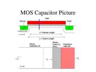
Proton Irradiation on MOS Capacitors Low ionising Conditions • 24 GeV protons are MIPs with reduced ionising capability • Generated Not densities drain out the nanometric oxide by tunneling processes • Low Nit densities are expected in low-hydrogen containing nm-thin oxides • Interface does not play the most relevant role in MOS capacitor C-V characteristics • Tox ranges at the nanometric scale (3-10 nm) • P-type silicon <100> substrate with boron doping concentration = 1015 cm-3 • Highly doped n-type polysilicon gate electrode
HF C-V curves in MOS Capacitors HF C-V Measurement Procedure • For low resistive substrates (~2 Ω·cm) Accumulation Inversion
Radiation Effects in MOS Capacitors TID effects • Oxide layer makes MOS capacitors sensitive to ionising damage • Total Ionising Dose (TID) induces the formation of oxide fixed charges (Not) and interface trap (Nit) densities. C-V characteristics experiences horizontal displacements with increasing D Interface traps • Nit induced displacement with increasing D Oxide Fixed Charges • The capacitance value in accumulation does not experience any modification as a consequence of TID induced effects • Not induced displacement with increasing D TID effects are expressed by the variation on the flat-band voltage values (ΔVfb) 8th Spanish Conference on Electronic Devices (CDE’11), Palma de Mallorca, Spain, February 2011 “Simulation of Total Ionising Dose in MOS Capacitors” P. Fernández-Martínez, F.R. Palomo, I. Cortés, S. Hidalgo and D. Flores.
Radiation Effects in MOS Capacitors DDD effects • Silicon substrate is sensitive to displacement damage. • Displacement Damage Dose (DDD) induces the formation of displacement defects within the volume of the substrate. M. Moll “Radiation Damage in Silicon Particle Detectors” UniveritätHamburg, PhD Dissertation, Chapter 3, 1999 • Electrically, displacement defects are identified with localised levels within the forbidden energy band gap. • Depending on the charge stored in the defects, the effective substrate doping concentration become modified by the presence of DDD induced defects. • Reduction of the effective doping concentration with increasing fluence P-type Substrates Increase of the effective substrate resistivity
Effect of the substrate resistivity Revista Mexicana de Física S 52(2) p.45-47, 2006 “Modelling the C-V characteristics of MOS capacitor on high resistivity silicon substrate for PIN photodetector applications”, J.A. Luna-López, M. Aceves-Mijares, O. Malik, R. Glaenzer HF C-V Measurement Procedure High Resistivity Low Resistivity MOS Capacitor complete electric model • Current measurement N-type substrate • Undepleted substrate resistance (Rs) becomes relevant as long as substrate resistivity is increased In highly resistive substrates, capacitance value in accumulation is no longer Cox
Effect of the substrate resistivity Sentaurus TCAD • Simulations: increase of the substrate resistivity => decrease in the substrate doping concentration • 4.48 Ω·cm • 8.79 Ω·cm • Drastic reduction of the accumulation capacitance Solid-State Electronics 36(4) pp.489-493, 1993 “Recalculation of Irvin’s Resistivity curves for diffused layers in Silicon using updated bulk resistivity data”, C. Bulucea P-type substrate
DDD Damage in Sentaurus TCAD IEEE Trans. Nucl. Sci., vol. 53, pp. 2971–2976, 2006 “Numerical Simulation of Radiation Damage Effects in p-Type and n-Type FZ Silicon Detectors”, M. Petasecca, F. Moscatelli, D. Passeri, and G. U. Pignatel • DDD defects are emulated by localised traps within the band-gap, with fluence dependent density: University of Perugia trap model P-type (FZ) Modified cross sections to match trapping times 10th RD50 Workshop, June 2007, Vilnius, Lithuania “Simulation results from double-sided and standard 3D detectors”, D. Pennicard, C. Fleta, C. Parkes, R. Bates, G. Pellegrini, and M. Lozano
Traps model: Simulation Sentaurus TCAD HF C-V Characteristic • Simulation Results with the trap model does not fit exactly the experimental data • With a proper model, simulations could be used to calibrate the capacitance-fluence relation P-type substrate • Capacitance reduction is qualitatively reproduced
Conclusions HF C-V • DDD effects are clearly distinguishable from TID effects on the HF C-V characteristics. • For MOS capacitors with nm-thick oxides TID effects can be considered negligible • Displacement damage effects on MOS capacitors induce a significant reduction of the capacitance value in accumulation. • The capacitance reduction is related with the received Displacement Damage Dose.
MOS Capacitor DDD Dosimeter • MOS Capacitor can be used as a simple DDD dosimeter • Both TID and DDD effects are produced on the device • HF C-V curves differentiated both effects • TID: Flat-band displacement • DDD: Reduction of the capacitance value in accumulation • For nanometric oxide thickness, TID effects are negligible • It can be monitored during irradiation • It can be easily integrated together with the technological process HF C-V
Thanks for your Attention • rogelio@gte.esi.us.es • School of Engineering, University of Sevilla, Spain