Download
1 / 1
40 likes | 213 Views
Lateral Load Behavior and Modeling of Low-Rise RC Walls for Performance-Based Design. Felipe Cifelli Home Institution: Florida International University REU Site: University of California , Los Angeles Project PI: Prof. John Wallace / Mentor: Thien Tran. Introduction. Results. Conclusion.

E N D
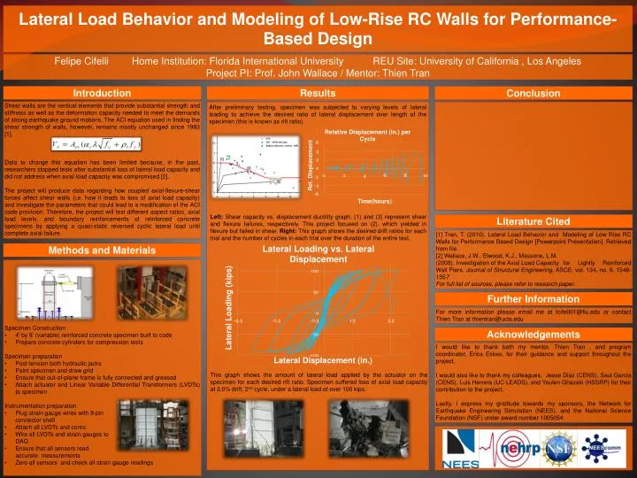
Lateral Load Behavior and Modeling of Low-Rise RC Walls for Performance-Based Design Felipe Cifelli Home Institution: Florida International University REU Site: University of California , Los Angeles Project PI: Prof. John Wallace / Mentor: Thien Tran Introduction Results Conclusion Shear walls are the vertical elements that provide substantial strength and stiffness as well as the deformation capacity needed to meet the demands of strong earthquake ground motions. The ACI equation used in finding the shear strength of walls, however, remains mostly unchanged since 1983 [1]. Data to change this equation has been limited because, in the past, researchers stopped tests after substantial loss of lateral load capacity and did not address when axial load capacity was compromised [2]. The project will produce data regarding how coupled axial-flexure-shear forces affect shear walls (i.e. how it leads to loss of axial load capacity) and investigate the parameters that could lead to a modification of the ACI code provision. Therefore, the project will test different aspect ratios, axial load levels, and boundary reinforcements of reinforced concrete specimens by applying a quasi-static reversed cyclic lateral load until complete axial failure. After preliminary testing, specimen was subjected to varying levels of lateral loading to achieve the desired ratio of lateral displacement over length of the specimen (this is known as rift ratio). Left: Shear capacity vs. displacement ductility graph. (1) and (3) represent shear and flexure failures, respectively. This project focused on (2), which yielded in flexure but failed in shear. Right: This graph shows the desired drift ratios for each trial and the number of cycles in each trial over the duration of the entire test. Literature Cited [1] Tran, T. (2010). Lateral Load Behavior and Modeling of Low Rise RC Walls for Performance Based Design[Powerpoint Presentation]. Retrieved from file. [2] Wallace, J.W., Elwood, K.J., Massone, L.M. (2008). Investigation of the Axial Load Capacity for Lightly Reinforced Wall Piers. Journal of Structural Engineering, ASCE, vol. 134, no. 9, 1548-1557 For full list of sources, please refer to research paper. Methods and Materials • Specimen Construction • 4’ by 8’ (variable) reinforced concrete specimen built to code • Prepare concrete cylinders for compression tests • Specimen preparation • Post-tension both hydraulic jacks • Paint specimen and draw grid • Ensure that out-of-plane frame is fully connected and greased • Attach actuator and Linear Variable Differential Transformers (LVDTs) to specimen • Instrumentation preparation • Plug strain gauge wires with 9-pin • connector shell • Attach all LVDTs and cores • Wire all LVDTs and strain gauges to • DAQ • Ensure that all sensors read • accurate measurements • Zero all sensors and check all strain gauge readings Further Information For more information please email me at fcife001@fiu.edu or contact Thien Tran at thientran@ucla.edu Acknowledgements I would like to thank both my mentor, Thien Tran , and program coordinator, Erica Eskes, for their guidance and support throughout the project. I would also like to thank my colleagues, Jesse Diaz (CENS), Saul Garcia (CENS), Luis Herrera (UC LEADS), and Youlen Ghazaki (HSSRP) for their contribution to the project. Lastly, I express my gratitude towards my sponsors, the Network for Earthquake Engineering Simulation (NEES), and the National Science Foundation (NSF) under award number 1005054. This graph shows the amount of lateral load applied by the actuator on the specimen for each desired rift ratio. Specimen suffered loss of axial load capacity at 3.0% drift, 2ndcycle, under a lateral load of over 100 kips.