Download
1 / 43
450 likes | 972 Views
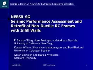
Seismic Performance Assessment and Retrofit of Non-Ductile RC Frames with Infill Walls. P. Benson Shing Ioannis Koutromanos Andreas Stavridis Marios Kyriakides Sarah Billington Kaspar Willam. NEES & PEER Quake Summit San Francisco, October 8-9, 2010. Masonry-Infilled RC Frames.

E N D
Seismic Performance Assessment and Retrofit of Non-Ductile RCFrames with Infill Walls P. Benson Shing Ioannis Koutromanos Andreas Stavridis Marios Kyriakides Sarah Billington Kaspar Willam NEES & PEER Quake Summit San Francisco, October 8-9, 2010
Masonry-Infilled RC Frames Complicated structural systems. Additional complexity introduced for older construction, where shear failures are expected in concrete columns. Mixed performance in past earthquakes. Collaborative research project to develop understanding of behavior, modeling techniques and retrofit schemes for masonry-infilled frames.
Cyclic Behavior of Infilled Frames Single-Story, single-bay, non-ductile reinforced concrete frames, infilled withsolid brick masonry panel, tested at CU Boulder by Willam et al.
Modeling Scheme Plane stress smeared cracking continuum elements to describe distributed cracking & crushing. Interface elements to describe strongly localized cracks as well as mortar joint cracking-sliding.
Modeling Approach – RC Columns Cracks are modeled in discrete and smeared fashion. Triangular smeared crack element Interface element to model discrete cracks Stavridis and Shing, 2010
Modeling Approach – Infill Panels Anticipated cracking pattern mainly runs through the mortar joints, with some brick splitting cracks Quadrilateral smeared crack elements (each elem. = half brick) Interface (for head joints) Interface (for bed joints) Interface (for possible splitting cracks) Stavridis and Shing, 2010
Smeared Crack Element Uncracked material: Failure surface combines Von Mises criterion with a tension cutoff criterion. Originally formulated by Lotfi and Shing (1992) σ2 ft σ1 ft σe σe Nonlinear isotropic hardening-softening law for effective strength Failure surface of uncracked material
Smeared Crack Element σ Exponential softening Initial stiffness unloading/reloading ft ε1 ε2 ε Secant stiffness unloading/reloading Exponential softening fc Parabola Cracked material: Orthotropic stress-strain law:
Interface Element n 3 4 1 t 2 Local coordinate system τ2 – μ2(σ – s)2 – 2r(σ – s) = 0 τ initial final μ, r, s: strength parameters 1 μο 1 Displacement vector: co = μ2so + 2roso ο μr 2 elastic so σ d = del + dpl+ dg geometric plastic Yield surface (Lotfi and Shing 1994)
Interface Element Koutromanos and Shing (2010) Loading-unloading Tensile Stress vs. Normal Crack Opening Reloading
Interface Element Axial Compression Shear Test on mortar joint by Mehrabi and Shing (1994) 100-psi Normal Compression Joint Dilatation & Compaction
Shake Table Test 1 EAST WEST
Prototype 3-story Building R/C frame with solid brick infill panels, representing design practice in California in the 1920s. Slab with joists
Base Acceleration Time Histories El Centro NS Record, 1940 Imperial Valley Earthquake Gilroy 3 000 Record, 1989 Loma Prieta Earthquake
Motion Sequence Stavridis et al, 2010
Specimen Damage Bottom Story Response After G67 ( = DE level)
Specimen Damage Bottom Story Response After G91 ( = MCE level)
Specimen Damage Bottom Story Response After G120
Final Test - Collapse El Centro 250% Motion
Verification – Shake Table Test 1 0.050 0.045 0.040 0.035 0.030 ζ 0.025 0.020 0.015 0.010 0.005 0.000 2.0 1.5 1.0 0.0 0.5 T(s) • Response is examined for a sequence of 5 motions: Gilroy 67% (twice), 83%, 91%, 100%, 120%. • Initial stiffness-proportional Rayleigh damping:
Bottom Story Drift Time Histories G120 Motion
Bottom Story Hysteretic Plots G83 motion G67 motion G67b motion G100 motion G120 motion G91 motion
Cracking Pattern Experiment Analysis After G91
Cracking Pattern Experiment Analysis After G100
Cracking Pattern Analysis Experiment After G120
Shake Table Test 2 Panel with ECC retrofit
Application of ECC Retrofit Dowels Anchors (1’ x 1’ grid) Unbonded dowels (with grease)
ECC Retrofit Behavior 1/5 scale specimens tested quasi-statically at Stanford University by Kyriakides and Billington. Unretrofitted Wall Retrofitted Wall No retrofit Lateral Load (kN) With ECC Retrofit Drift (%)
Damage at Specimen Frame/panel separation
Second Story Strengthening Epoxy injections at major cracks GFRP overlay (by Fyfe Co.) 1 layer of Tyfo SEH-51A System, Oriented Horizontally 1 layer of Tyfo SEH-51A System Oriented Vertically 12” 12” 1 layer of Tyfo BC
Motion Sequence T1 before testing T1 after testing MCE DE
Effectiveness of 2nd Story Repair Before FRP Retrofit After FRP Retrofit
Bottom Story Response specimen 1 peak specimen 1 peak 1Damage due to previous motions
Final Damage Signs of delamination joint failure Failure of top ECC/frame shear dowel connection
Shear/sliding Crack at Bottom Story Failure of shear dowels
Conclusions • Infills can significantly increase the lateral strength of a non-ductile frame, thus improving seismic performance. • Retrofit using ECC overlay increased the resistance of the infilled frame, however it may not always be possible to increase ductility. • Repair based on epoxy injection/GFRP is fast and efficiently restores the strength of an infill panel.
Conclusions • The proposed analysis methodology offers satisfactory agreement with recorded data in terms of global response quantities and failure mechanism. • Further numerical investigation of system performance for different configurations is feasible.
Acknowledgements • Research sponsored by NSF (under the Network for Earthquake Engineering Simulation Research Program). - Professional Advisory Panel: Joe Maffei, John Kariotis, David Breinholtz, Michael Valley, Gregory Kingsley, Ronald Mayes. • Johnson Western Gunite Company. • Fyfe Co. (Scott Arnold).
Thank you • Questions?