Download
1 / 40
400 likes | 512 Views
IP Based Network Concepts & Overview. Faculty of Network Planning ALTTC, Ghaziabad. Introduction. Standalone computers. Computers in a network.

E N D
IP Based Network Concepts&Overview Faculty of Network Planning ALTTC, Ghaziabad.
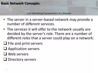
Introduction • Standalone computers. • Computers in a network. • Different applications/services between computers: e-mail, File Transfer, Remote Login, Web Surfing, Network Management, chatting, playing games etc.
Introduction • To achieve interworking between computers & other devices like servers, routers etc the computer is made to work in a hierarchical manner ie it is to work as a layered model. Each layer doing certain functionalities & offering services to its upper layer.
Introduction • International Standard Organisation (ISO) devised a 7 layered model called Open System Interconnection (OSI model) APPLICATION APPLICATION PRESENTATION PRESENTATION SESSION SESSION TRANSPORT TRANSPORT NETWORK NETWORK DATA LINK DATA LINK PHYSICAL PHYSICAL B A
Introduction • Each computer has this OSI model embedded in it. • Whenever any computer wants to communicate with any other computer or entity it will adopt a set of rules agreeable to all the computers & entities in the network. This set of rules is called Protocol. Each layer communicates with its peer layer using a protocol before actual data transfer takes place.
Introduction So we require a stack of protocol called Protocol Suite to effect communication between computers in a network. Different protocol suites are available like: (a) AppleTalk (d) TCP/IP (b) OSI (e) DECnet (c) IPX/SPX (f) XNS
IP Protocols • Internet or IP technology over the years has emerged as the most prominent data communication technology. • TCP/IP protocol has become de-facto data comm standard throughout the world. • It can carry even voice/video also over IP protocol and in turn has started challenging the complete monopoly of TDM technology in voice communication.
APPLICATION APPLICATION PRESENTATION SESSION TCP/IP Model OSI Model TRANSPORT TRANSPORT NETWORK NETWORK DATA LINK DATA LINK PHYSICAL PHYSICAL TCP/IP and OSI • OSI is made of seven layers. • TCP/IP protocol is made of five layers.
FTPSMTPTELNETHTTP TFTPNFSSNMPDNS A T TCP UDP ICMP IGMP ARP RARP N IP Ethernet, Token Ring, FDDI, HDLC, FR, PPP, ATM D Protocols defined by the underlying networks P TCP/IP Protocol Suite
Application Data TCP Header Data TPT Layer UDP Message TCP Segment UDP Header Data NW Layer IP Header TCP-UDP Data IP Datagram Data Link Frame Head IP Header TCP-UDP Data Trailer Frame Data Encapsulation
Internet Control Message Protocol • Internet Control Message Protocol is a mechanism used by hosts and routers to send notification of datagram problems back to the sender. • Sends error messages only to the source and not to intermediate routers. • Sole function is to report problems, not to correct them. • ICMP (Ping- Packet Internet Gropher) uses echo/reply to test whether a destination is reachable and responding.
Address Resolution Protocol • Address Resolution Protocol is used to translate 32 bits IP addresses to 48 bits Ethernet addresses. • A host’s physical address is determined by broadcasting its IP address to all machines. • The machine with matching IP address, in broadcast message, sends its hardware address to the machine originating broadcast.
Here is my MAC address Give me MAC address of 129.1.1.4 129.1.1.1 129.1.1.4 ARP Response Accepted That’s Me 129.1.1.2 129.1.1.3 ARP Operation Request Ignored Request Ignored
Reverse Address Resolution Protocol • Reverse Address Resolution Protocol is used to get the 32 bits Source IP address, knowing the 48 bits Hardware address. • It is reverse of ARP, hence named Reverse Address Resolution Protocol. • A diskless workstation broadcasts RARP-Request to find its IP Address at the time of boot up.
Give me my IP address RARP Response Diskless work station RARP Server 08-00-39-00-2F-AB 223.1.2.3 223.1.2.1 08-00-39-00-2F-C3 223.1.2.2 08-00-10-99-AC-54 08-00-5A-21-A7-22 RARP Operation
32 Bits Network Host IPv4 Address 8 Bits 8 Bits 8 Bits 8 Bits 172 . 16 . 122 . 204
NAT (Network Address Translation) • Private addressing • Public IP Addressing • Address translation
Class-A: N H H H Class-B: N N H H Class-C: N N N Class-D: For Multicast Class-E: For Research IPv4 Address Classes H Present day Internet does not use Class full addressing, Instead Classless addressing is used.
IPV6 • IP version 4 has got 32 bit IP addressing scheme. • With the explosive growth of Internet there is a severe shortage of IP addresses as every host on internet should have an IP address. • To overcome the shortage of IPV4 IP addresses IPV6 has been designed which has 128 bit IP addressing scheme. • To implement IPV6 in the network all IPV4 network elements are to be replaced with IPV6 devices as they are directly not compatible.
Segment - A segment is any portion of a network that is separated, by a switch, bridge or router, from other parts of the network. • Network Interface Card (NIC) - Every computer (and most other devices) is connected to a network through a NIC. This is usually an Ethernet card (normally 10 or 100 Mbps) that is plugged into a slot on the computer's motherboard. • Media Access Control (MAC) address - This is the physical address of any device -- such as the NIC -- on the network. MAC address is made up of two equal parts (6 bytes long). The first 3 bytes identify the company that made the NIC and the second 3 bytes are the serial number of the NIC itself.
HUB vs SWITCH • A vital difference between a hub and a switch is that all the nodes connected to a hub share the bandwidth among themselves, while a device connected to a switch port has the full bandwidth all to itself. • For example, if 10 nodes are communicating using a hub on a 10-Mbps network, then each node may only get a portion of the 10 Mbps if other nodes on the hub want to communicate as well. But with a switch, each node could possibly communicate at the full 10 Mbps.
LAN Switch • Most switches operate at the Data layer (Layer 2) but some incorporate features of a router and operate at the Network layer (Layer 3) as well. • Router: When a router receives a packet, it looks at the Layer 3 source and destination addresses to determine the path the packet should take. • Standard Switch: This relies on the MAC addresses to determine the source and destination of a packet, which is Layer 2 (Data) networking. • Layer 2 vs. Layer 3 switch: L3 switches have optimized hardware to pass data as fast as Layer 2 switches, yet they make decisions on how to transmit traffic at Layer 3, just like a router.
Router • Router is a layer 3 device which can look into the destination IP address of an IP packet and with the help of its routing table it can forward the packet to appropriate direction. • Routers have many interfaces to connect LANs and WANs. • Routers can build their routing table automatically with the help of various routing protocols. • Routers share their information with their neighboring routers to build routing tables.
Routers • Internet can be considered as thousands of routers connected with each other in criss-cross manner. • Routers can be deployed by a carrier in the core to create the backbone and the customers routers get connected to the backbone. • Customer’s routers act as gateway for their network.
Static - Dynamic Routing • Static/Non Adaptive • Choice of route is computed in advance, off line, and downloaded to the router when network is booted. • Dynamic/Adaptive • Routing decisions change to reflect the changes in topology and/or traffic.
Static Routing • Routes to destinations are set up manually. • Network reachability is not dependent on the existence and state of the network. • Route may be up or down but static routes will remain in the routing tables and traffic would still be sent towards the route. • Not suitable for large networks.
Default Routing • When a router receives a packet and its table does not contain the network number indicated in the packet, it is forwarded to default router. • The default router, too, may have a default route. • If there is no route or default route at any stage, the router will send a control message (through ICMP) to the originating station.
Dynamic Routing • Routes are learnt via an internal or external routing protocols. • Network reachability is dependent on the existence and state of the network. • If a router is down, its entry will be deleted from the routing table and traffic to that will not be forwarded. • Used to enable routers to build their own routing tables and make appropriate decisions.
Routing Protocol • It is a language a router speaks with other routers to share information about the reachability and status of the network. • Provides mechanisms for sharing routing information. • Allows the routers to communicate with other routers to update and maintain routing tables.
Routing Protocol • Routing Protocol messages do not carry end user traffic from network to network. • Routing Protocol uses the routed protocol ( e.g. IP)to pass information between routers. • RIP & OSPF are routing protocols.
Radius Server • RAS Support for RADIUS authentication and RADIUS Accounting • Irrespective of mode of access (such as Dial-up Internet access,outsourced remote access ,managed VPNs, Broadband etc),it will manage the Authentication of all users/customers- both locally and via proxy RADIUS- and deliver the appropriate level of service to each customer. • RADIUS will support interfacing with LDAP based authentication, billing and Provisioning systems. • It will include advanced proxy RADIUS support.It will be able to act as a proxy target server, and can forward proxy requests to other RADIUS servers. • It will load balance authentication requests between several SQL or LDAP databases, to eliminate the risk of a single point failure, and increase performance on busy networks. • The RADIUS will generate CDRs for the Billing system and the CDRs will contain the following information • The calling IP address allotted by the RADIUS • Start Time and Date • End Time and Date • Volume of data transmitted and port type.
LDAP (Directory Server)Light weight Directory Access Protocol • The Directory Server shall support unlimited number of read only consumers for authentication queries. • The Directory Server shall support Class of Service and Role based mechanism. • The Directory Server shall support Storage of Digital Certificates. • The LDAP and RADIUS will be able to handle a customer base of 8 Lakhs assuming a concurrency rate of 40% . • The authentication will not take more than 1 sec under the full load.
Remote Access Server (RAS) • RAS is a device which allows a customer to access internet through his telephone line by dialing an access code. • RAS is an interface between PSTN and Internet. • Before allowing the access RAS authenticates the dial up user with the help of RADIUS sever. • RAS is having circuit switched interface with PSTN and packet switched interface with Internet.
Remote Access Server (RAS) Internet Node RAS E1s or PRI PSTN Router Modem Internet LAN Switch
Domain Name System (DNS) • DNS is a mechanism which translates host name to IP address in Internet • All the network elements in Internet understand only IP address. To reach a site host name is to be converted to IP address. • DNS servers in the Internet search IP address of these host names.
What is the IP Address of www.Yahoo.com What is the IP Address of www.Yahoo.com www.yahoo.com , IP address is 210.212.90.15 User traffic www.yahoo.com , IP address is 210.212.90.15 Domain Name System (DNS) DNS Server DNS Server Internet yahoo.com