Download
1 / 14
140 likes | 144 Views
Carelessly or improperly operated CNC Machines can cause serious injury or death as well as damage or destruction of equipment. Download fadal diagnostic system maintenance manual thoroughly covers the command, warning of all CNC parts. <br>The emergency and safety procedures in this manual are to help users operate the CNC in a safe manner. Fadal has no control over the applications the operator may use the CNC for and is not responsible for injuries or equipment damage. Read and understand the Operatoru2019s Manual. For more queries, contact us at parts@itscnc.com<br><br>https://itscnc.com/fadal-manuals

E N D
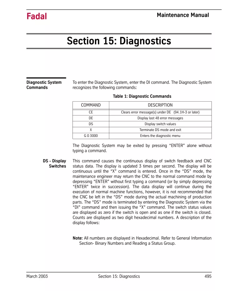
Fadal Maintenance Manual Section 15: Diagnostics To enter the Diagnostic System, enter the DI command. The Diagnostic System recognizes the following commands: Diagnostic System Commands Table 1: Diagnostic Commands COMMAND DESCRIPTION CE Clears error message(s) under DE (94.1H-3 or later) DE Display last 48 error messages DS Display switch values X Terminate DS mode and exit G 0 3000 Enters the diagnostic menu The Diagnostic System may be exited by pressing “ENTER” alone without typing a command. This command causes the continuous display of switch feedback and CNC status data. The display is updated 3 times per second. The display will be continuous until the “X” command is entered. Once in the “DS” mode, the maintenance engineer may return the CNC to the normal command mode by depressing “ENTER” without first typing a command (or by simply depressing “ENTER” twice in succession). The data display will continue during the execution of normal machine functions, however, it is not recommended that the CNC be left in the “DS” mode during the actual machining of production parts. The “DS” mode is terminated by entering the Diagnostic System via the “DI” command and then issuing the “X” command. The switch status values are displayed as zero if the switch is open and as one if the switch is closed. Counts are displayed as two digit hexadecimal numbers. A description of the display follows: DS - Display Switches Note: All numbers are displayed in Hexadecimal. Refer to General Information Section- Binary Numbers and Reading a Status Group. March 2003 Section 15: Diagnostics 495
Fadal Maintenance Manual . Table 2: Display Switches DISPLAY DESCRIPTION DISPLAY DESCRIPTION ATCXTNDD Switch closes when the ATC slide is extended ATCTURET Switch closes momentarily when the ATC turret motion is com- plete. May not be seen because closure may occur between screen updates. ORIENSP Switch closes when the spindle is at the proper angle for orienta- tion. ATCHOME Switch closes when the ATC slide is fully retracted. ATCFAULT Switch closes when the ATC is subjected to excessive up or down forces. DRAWBAR Switch closes when the drawbar cylinder is pressurized. OIL LEVEL Switch closes when the oil level is low for waylube and spindle lube reservoir. HIGH IDLER Switch closes when the idler wheel is retracted. (Low range engaged). LOW IDLER Switch closes when the idler wheel is retracted. (High range engaged). PROBE Switch is open when probe switch is engaged. SLIDE HOLD Switch is open when doors are closed (external slide hold). COMMAND1 Refer to Hex to Binary table Each binary bit commands one solid state relay. A value of 0 turns the relay on. B0 is the rightmost bit. B0= M68/M69 B1= High range idler B2= Unused B3= Drawbar/Geneva/Slide Enable B4= Drawbar B5= Air indexer B6= Coolant 1 ON B7= Coolant 2 ON 496 Section 15: Diagnostics March 2003
Fadal Maintenance Manual Table 2: Display Switches DISPLAY DESCRIPTION COMMAND2 Refer to Hex to Binary table Each binary bit commands one solid state relay. A value of 0 turns the relay on. B0 is the rightmost bit. B0= Unused B1= Low range idler B2= M62/M63 B3= M66/M67 B4= Turret motor ON B5= Turret motor reverse B6= Spindle coolant pump B7= M64/M65 COMMAND3 Refer to Hex to Binary table Each binary bit commands one solid state relay. A value of 0 turns the relay on. B0 is the rightmost bit. B0= Orientation B1= ATC Slide motor ON B2= ATC slide motor REVERSE B2= ATC slide motor REVERSE B3= Way lube pump B4= Limit switch override B5= M60/M61 B6= Axis amplifier ON/OFF B7= Spindle lubricator ON (MEMORY) Contents of the memory location specified with the DS command. For example DS A5A5 will cause the display of the contents of memory location A5A5 (A5A5 is a hexadecimal address). LASTMFUN The BCD value of the last M-function. MFUNFDBK The M-function feedback data from user attached devices. INT1-CNT Running count of CRT screen update clock interrupt. INT2-CNT Running count of 100 ms clock interrupts. INT3-CNT Running count of axis controller interrupts. INT4-CNT Running count of RS232-C port interrupts. INT5-VAL Last data from keyboard (ASCII with B7=1) INT6-CNT Running count of geometric algorithm interrupts. INT7-CNT Running count of Emergency stop interrupts. SPARE-3 Probe feedback switch SPARE-6 Air indexer feedback switch #2 SPARE-7 Air indexer Feed back switch #1 March 2003 Section 15: Diagnostics 497
Fadal Maintenance Manual Menu Diagnostics WARNING Some of these tests are intended for Fadal factory use only. Use only those tests that the Maintenance technician has been trained to use. Call the Fadal Service Department for more information. ! ! AVAILABLE IN SYSTEMS 89.1I (and above) One of the new features available to the 89 series software is the diagnostics menu. This feature is useful in testing the 1400-2 or higher CPU card, Ram Expansion, RS-232 Port, Video, Axis Controllers, Clocks, and the Mill Interface. Although the tests are designed not to affect memory it is still a good idea to make sure all the programs on the machine are backed up before testing. To begin, at the prompt “ENTER NEXT COMMAND” enter the following commands: DI <ENTER> G 0 3000 <ENTER> After entering the above commands, the first of 5 menus will appear. The space bar switches between each menu and the MANUAL key is used to abort a test (Hold this key down until the computer aborts a test). Function 1 = EPROM CHECKSUM (1610-1) Reads the eproms on the 1610 MODULE CARD. After performing the checksum, the result is displayed. This test displays four to six 1 byte numbers. They should be all zeros. If they are all zeros, the test counter is incremented and the test is repeated. The message “CHECKSUM ERROR” is displayed and the test stops if the checksum is not zero. A failure with the test would indicate a bad CPU card or MODULE. Menu Page 1 Function 2 = RAM TEST (1400) Performs a write/read test to the 1400 CPU memory. This memory is used by the CPU for such things as parameters, offsets, execution buffers, general usage of the CPU. While the test is running the current memory segment is displayed as follows: SEGMENT 6 or 4 SEGMENT 7 or 5 SEGMENT 8 PASSED TEST #### TIME(S) 498 Section 15: Diagnostics March 2003
Fadal Maintenance Manual The message “MEMORY FAILURE” would appear and the data that failed is displayed. A failure with this test indicates the 1400 card needs to be replaced. Function 3 = RAM EXPANSION TEST (1460) Tests is the same as function 2 except it searches for the available memory expansion. Checks up to 422K. SEGMENT 9 SEGMENT A SEGMENT B SEGMENT C SEGMENT D SEGMENT E PASSED TEST #### TIME(S) If the card is present, it is tested automatically the same as function 2. When a card is not found the message “NOT PRESENT” appears next to the segment number. Refer to the Attached Optional Devices Section for setting the memory card to the proper segment (1460-2 has no jumper settings). Note: A more thorough RAM test is available on MENU PAGE 5. Function 4 = RS-232 TEST (1030) Tests the RS-232 port. You must install the test plug supplied by FADAL (located in the main cabinet) or jumper pins 2 and 3. After selecting the baud rate number, the CNC sends and receives a continuous flow of characters until an error has occurred or the manual key is pressed. There are two procedures that can be performed with this test. 1) Install the plug directly in the back of the CNC and cycle the test. This checks the machine for a possible failure with the ribbon cable, wiring or the S-100 (1030) card. 2) Install the test plug at the computer’s end of the cable. This will check not only the cable but also the environment. A bad cable, solder connection or an electrical noise problem could cause the first test to pass and the second test to fail. Function 5 = NON-DESTRUCTIVE LOOP TEST Causes all tests to be continuously performed until a failure has occurred or the manual key is pressed. Program memory checksum (menu page 3) and all functions on menu pages 4 and 5 will not execute during the loop test. March 2003 Section 15: Diagnostics 499
Fadal Maintenance Manual Function 1 = KEYBOARD TEST Tests the keyboard by echoing the key to the screen. Pressing the JOG key allows the hand wheel to be tested. Menu Page 2 CAUTION! Check SETP parameters after performing this test. Function 2 = START CNC DO NOT USE Function 3 = 1010-4 AXIS CONTROLLER DIAGNOSTICS INTENDED FOR FADAL USE ONLY! Function 4 = START MOS INTENDED FOR FADAL USE ONLY! Function 5 = ZERO MEMORY On the 1400-2 writes zeros to segments 6,8,9,A,B,C,D,E. On the 1400-3 writes zeros to segments 4,5,8,9,A,B,C,D,E. WARNING: This will clear all memory SETP, backlash user programs, tool and fixture information. Function 1 = VIDEO TEST (1420) This test has two functions. Menu Page 3 1) A testing of the video ram, which you will see as a quick flicker on the screen. If a failure is reported then there is a possible failure on the 1420-1 (video board) or the 1030-1 on the -3 system. 2) A visual test. The screen should show a repeating pattern of characters. If the pattern is not repeating then there is a possible failure on the 1420-1 (video board) or the 1030-1 on the -3 system. Function 2 = 1010-1 OR 1010-4 AXIS CONTROLLER TEST Tests all the axes, X, Y, Z, A, B, and C. If an axis slot is not populated then the No Response counter will be incremented. If an axis slot is populated and either the No Response counter or the Failure counter has been incremented then there is a possible failure of that card (computer interface 1030) or even possible failure of the CPU. Note that the expected and the received checksum the spindle card is F0 and 80 respectively. Function 3 = TEST THE CLOCKS (1020) All three of the VMC’s clocks will be tested with this function. Interrupt 6 counts from -200 to 0 and then interrupts, interrupt 2 interrupts after approximately 500 Section 15: Diagnostics March 2003
Fadal Maintenance Manual 0.1 seconds, and interrupt 3 interrupts after approximately 0.3 seconds. Therefore, as interrupt 1 counts to 0 interrupt 3 should count to about 6 (Note that the counting doesn’t have to be perfect but should be in the general area). A message should appear if an interrupt is not counting properly. A failure could indicate a problem with the clock card or communication problem with the computer interface or CPU. To exit this test you must wait till the exit message “... PRESS MANUAL TO STOP TEST” appears. At the time of the exit message press the manual key to exit the test. Function 4 = TEST MILL INTERFACE CARD (1040) Checks the mill interface. The pass counter will be incremented with each successful pass. Otherwise, a failure message will appear, which possibly indicates a 1040 failure. This test only checks the communication portion between the 1040 and 1030 to 1400. Function 5 = PROGRAM MEMORY CHECKSUM Calculates a four byte checksum of all the current programs in memory. This checksum is used to verify that the memory has not been changed during a power on/off test or during a long period of time with the power off. Function 1 = FILL MEMORY WITH A PATTERN INTENDED FOR FADAL USE ONLY! Menu Page 4 Function 2 = CHECK MEMORY FOR PATTERN INTENDED FOR FADAL USE ONLY! Function 3 = ENABLE/DISABLE REMOTE DIAGNOSTICS INTENDED FOR FADAL USE ONLY! Function 4 = ECHO RS-232 PORT DATA The CNC’s back serial port will act just like a test plug. It will echo back any data that it receives on the port. Function 5 = DESTRUCTIVE RAM TEST INTENDED FOR FADAL USE ONLY! Function 1 = COUNT INT1, INT2 AND INT6 INTENDED FOR FADAL USE ONLY! Menu Page 5 Function 2 = FULL DAC WITH INT6 COUNT 0FED4H INTENDED FOR FADAL USE ONLY! March 2003 Section 15: Diagnostics 501
Fadal Maintenance Manual Function 3 = QUARTER DAC WITH INT6 COUNT 0FED4H INTENDED FOR FADAL USE ONLY! Function 4 = TEST ENCODERS (1010-4) Tests any encoder connected to a 1010-4 axis card. AC Machines. Function 5 = TEST ADC INTENDED FOR FADAL USE ONLY! Clamp-on Ammeter Testing The purpose of the procedure is to monitor the amount of current that the axis motor is using to transverse the slide. The ExTech AC/DC Clamp-On ammeter can be used as an indicator for various problems, including: ballscrew alignment, gib and/or gib straps adjustments, insufficient or incorrect waylube, and to check for tightness of the limit stop at the axis limit. Tooling Required: ExTech AC/DC Clamp-On Ammeter This procedure should only be done to check gib and gib strap adjustments for binding. It is not intended to be a replacement for the procedure outlined in the Maintenance Manual. Gib and Gib Strap Verification 1) Set the Clamp-On Ammeter to the following selections: ON, DC, 200A and adjust the display to 00.0 with DCA ZERO ADJ. 2) Attach the ExTech AC/DC Clamp Meter over the brown wire on the axis amplifier to be checked. Ensure that the jaws remain closed when hanging from the wire. Be careful not to touch the DCA ZERO ADJ. knob, as the readings will be distorted. 3) Jog the axis to the + (plus) limit. 4) Enter one of the following into MDI, adjusting values to reflect the total travel of this axis. For example, VMC4020 has the values of X=40, Y=20, Z=20. a) G1 F25. G91 X?_. M49 b) GI F25. G91 Y?_. M49 c) G1 F25. G91 Z?_ M49 5) Monitor the display on the Clamp Meter while traversing along the axis and record the average reading. note that the current reading may rise 1 or 2 amps near the ends from ramping. 502 Section 15: Diagnostics March 2003
Fadal Maintenance Manual 6) Normal readings for Millimeter ballscrews range from 4 to 6. 5 amps and for Inch ballscrews the range is from I to 2.5 amps. 6030 & 8030 4 to 6, 7 amps max. 7) For higher than normal readings, check the following items: a) Is the proper waylube being used, and the waylube system operating properly? Refer to the Machine Maintenance Section. b) Do the ways have the proper amount of waylube? c) Loosen the gibs slightly and rerun the above test. Are the new readings less than the original readings? If yes, repeat again until the readings no longer change. 1) Set the Clamp-On Ammeter to the following selections: ON, DC, 200A, and adjust the display to 00.0 using the DCA ZERO ADJ. Ballscrew Alignment 2) Attach the ExTech AC/DC Clamp Meter over the brown wire on the axis amplifier to be checked. Ensure that the jaws remain closed when hanging from the wire. Be careful not to touch the DCA ZERO ADJ. knob, as the readings will be distorted. 3) Jog the axis to the + (plus) limit. 4) Enter one of the following into MDI, adjusting values to reflect the total travel of this axis. For example, VMC4020 has the values of X=40, Y=20, Z=20. a) GI F25. G91 X-_. M49 b) GI F25. G91 Y- _. M49 c) GI F25. G91 Z-_ M49 5) Monitor the Ammeter display while traversing along the axis. The readings should not vary more than 2 amps for Millimeter ballscrews and 1 amp for Inch ballscrews. 6) Watch for variations as either end is approached. If higher than normal values, check and adjust ballscrew alignment. 7) If the ballscrew is realigned, then readjust backlash and retest. 1) Set the Clamp-On Ammeter to the following selections: ON, DC, 200A and adjust the display to 00.0 with DCA ZERO ADJ. Limit Stop Check 2) Attach the ExTech AC/DC Clamp Meter over the brown wire on the axis amplifier to be checked. Ensure that the jaws remain closed when hanging from the wire. Be careful not to touch the DCA ZERO ADJ. knob, as the readings will be distorted. March 2003 Section 15: Diagnostics 503
Fadal Maintenance Manual 3) Jog the axis to the + (plus) limit. 4) Enter one of the following into NMI, adjusting values to reflect the total travel of this axis. For example, VMC4020 has the values of X=40, Y=20, Z=20. a) GI F25. G91 X-_. M49 b) GI F25. G91 Y-_. M49 c) GI F25. G91 Z-_ M49 5) Check the reading on the meter when the axis has reached the limit and stopped. Normal readings should be no higher than 2 amps than the average? current reading along the travel of the axis. Refer to AXIS LIMIT STOP, MECHANICAL ADJUSTMENTS, in the Axis Drive Systems Section. 6) Now, check the opposite direction wire by clamping the meter on the WHITE wire at the amplifier output. 7) Enter one of the following into MDI, adjusting values to reflect the total travel of this axis. For example, VMC4020 has the values of X=40, Y=20, Z=20. a) GI F25. G91 X_. M49 b) GI F25. G91 Y. M49 c) GI F25. G91 Z_. M49 8) Check the reading on the meter when the axis has reached the limit and stopped. Normal readings should be no higher than 2 amps than the average current reading along the travel of the axis. Refer to AXIS LIMIT STOP, MECHANICAL ADJUSTMENTS, in the Axis Drive Systems Section. Test Cut Procedure 1) Use program 5836 2) Install test cut block in center (T) slot, and center under spindle. Pull block forward and tighten bolts. 3) In MDI type S600. M3 M49.<ENTER> Turn spindle on to establish RPM of spindle turn spindle off using spindle off key. 4) Insert tool with edge finder in spindle and turn on spindle with SHIFT-- SPINDLE ON KEYS. 5) Jog Z down to the front edge of part and set edge finder by jogging Y-axis plus or minus. 504 Section 15: Diagnostics March 2003
Fadal Maintenance Manual 6) Jog Z up away from part. 7) Turn spindle off. 8) Do not move Y axis. In MDI type Y.1GO <ENTER>. 9) At enter next command type SETY The Y-axis is now set. 10) Turn on spindle with SHIFT-SPINDLE ON KEY. 11) To set X axis, jog to right side of part and jog down Z axis, making sure not to hit edge finder on top of part when jogging. Set X axis the same way that Y axis was set. 12) Turn off spindle. Do not move X axis in MDI type X-,1G0 <ENTER>. 13) At enter next command TYPE SETX. The X axis is now set. 14) Remove tool with edge finder from spindle. Install tool with cutter in spindle. 15) Use a 1.00 INCH BLOCK to set the Z tool height. Set block on top of par.t Jog Z down until the Z just touches the block. At the ENTER NEXT COMMAND prompt, type sl,12 <ENTER>. 16) At ENTER NEXT COMMAND type HO <ENTER>. 17) At ENTER NEXT COMMAND type DT<ENTER>. 18) Type # 1. 19) Then #12 <ENTER>. 20) Change to .48 TOOL DIAM. 21) Change tool length by -.001. 22) Press #1 to accept. 23) Set spindle pot and feed rate pot to 100%. 24) At enter next command type AU,28,75<ENTER> and start program. March 2003 Section 15: Diagnostics 505
Fadal Maintenance Manual 1) Push test part towards back of fixture. VMC Test Cut 2) Home position: X - as shown below Y - as shown below Z - coldstart position 3) Program 5836 (TA,2). 4) Set tool length 1" above part (SL,12). Tool length may have to be altered if top of part doesn't get cut. 5) Use 1/2" diameter 4 flute carbide endmill. Set tool diameter at .480 for initial cut (lower tool diameter if recut is necessary). 6) Edit program as indicated below (if necessary). 7) Start program @ N28 and stop @ N75. (AU,28 <ENTER>) 506 Section 15: Diagnostics March 2003
Fadal Maintenance Manual VMC Test Cut Part 1) Belts 2) X Motor 3) Y Motor 4) Belt / End Mill/Spindle Preload Spindle Motor Washer 5) Comp./Bad Axis Motor March 2003 Section 15: Diagnostics 507
Fadal Maintenance Manual (This page intentionally left blank). 508 Section 15: Diagnostics March 2003