Download
1 / 12
150 likes | 940 Views
Prof. Brian L. Evans Dept. of Electrical and Computer Engineering The University of Texas at Austin. Quadrature Amplitude Modulation (QAM) Receiver. Outline. Introduction Automatic gain control Carrier detection Symbol clock recovery Channel equalization QAM demodulation. Introduction.

E N D
Prof. Brian L. Evans Dept. of Electrical and Computer Engineering The University of Texas at Austin Quadrature Amplitude Modulation (QAM) Receiver
Outline • Introduction • Automatic gain control • Carrier detection • Symbol clock recovery • Channel equalization • QAM demodulation
Introduction • Channel impairments Linear and nonlinear distortion of transmitted signal Additive noise (often assumed to be Gaussian) • Mismatch in transmitter/receiver analog front ends • Receiver subsystems to compensate for impairments Fading Automatic gain control (AGC) Additive noise Matched filters Linear distortion Channel equalizer Carrier mismatch Carrier recovery Symbol timing mismatch Symbol clock recovery
Baseband QAM i[m] Transmitter i[n] L gT[m] Index s[m] cos(cm) Bits s(t) Serial/parallelconverter Map to 2-D constellation Pulse shapers(FIR filters) + sin(c m) D/A J 1 q[m] L samples/symbolm sample indexn symbol index L gT[m] fs q[n] c(t) QAM Demodulation Receiver Carrier Detect AGC X LPF L r1(t) r0(t) r(t) r[m] Receive Filter A/D ChannelEqualizer 2 cos(cm) Symbol Clock Recovery X LPF L Carrier recovery is not shown -2 sin(cm)
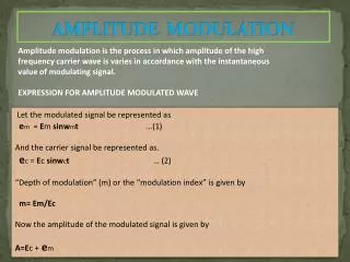
c(t) AGC r1(t) r(t) r[m] A/D Automatic Gain Control • Scales input voltage to A/D converter Increase gain for low signal level Decrease gain for high signal level • Consider A/D converter with 8-bit signed output When c(t) is zero, A/D output is 0 When c(t) is infinity, A/D output is -128 or 127 Let f-128, f0 and f127 represent how frequently outputs -128, 0 and 127 occur over a window of previous samples Each frequency value is between 0 and 1, inclusive Update: c(t) = (1 + 2 f0 – f-128 – f127) c(t – t) Initial values: f-128 = f0 = f127 = 1 / 256. Zero also works.
Carrier Detection • Detect energy of received signal (always running) c is a constant where 0 < c < 1 and r[m] is received signal Let x[m] = r2[m]. What is the transfer function? What values of c to use? • If receiver is not currently receiving a signal If energy detector output is larger than a large threshold, assume receiving transmission • If receiver is currently receiving signal, then it detects when transmission has stopped If energy detector output is smaller than a smaller threshold, assume transmission has stopped
Symbol Clock Recovery • Two single-pole bandpass filters in parallel One tuned to upper Nyquist frequency u = c + 0.5 sym Other tuned to lower Nyquist frequency l = c– 0.5 sym Bandwidth is B/2 (100 Hz for 2400 baud modem) • A recovery method Multiply upper bandpass filter output with conjugate of lower bandpass filter output and take the imaginary value Sample at symbol rate to estimate timing error Smooth timing error estimate to compute phase advancement Pole locations? See Reader handout M when Lowpass IIR filter
Channel Equalizer • Mitigates linear distortion in channel • When placed after A/D converter Time domain: shortens channel impulse response Frequency domain: compensates channel distortion over entire discrete-time frequency band instead of transmission band • Ideal channel Cascade of delay D and gain g Impulse response: impulse delayed by D with amplitude g Frequency response: allpass and linear phase (no distortion) Undo effects by discarding D samples and scaling by 1/g g z-
Channel Equalizer • IIR equalizer Ignore noise nm Set error em to zero H(z) W(z) = gz-D W(z) = gz-D / H(z) Issues? • FIR equalizer Adapt equalizer coefficients when transmitter sends training sequence to reduce measure of error, e.g. square of em Discrete-Time Baseband System nm Channel Equalizer ym xm rm em w h + + + Training sequence - Ideal Channel Receiver generatesxm g z-
Adaptive FIR Channel Equalizer • Simplest case: w[m] = d[m] + w1d[m-1] Two real-valued coefficients w/ first coefficient fixed at one • Derive update equation for w1 during training Using least mean squares (LMS) Step size 0 < m < 1 nm Channel Equalizer ym xm rm em w h + + + Training sequence - Ideal Channel Receiver generatesxm sm g z-
Baseband QAM Demodulation • Recovers baseband in-phase/quadrature signals • Assumes perfect AGC, equalizer, symbol recovery • QAM modulation followed by lowpass filtering Receiverfmax = 2 fc + B and fs > 2 fmax • Lowpass filter has other roles Matched filter Anti-aliasing filter • Matched filters Maximize SNR at downsampler output Hence minimize symbol error at downsampler output X LPF x[m] 2 cos(cm) X LPF -2 sin(cm)
Baseband QAM Demodulation • QAM baseband signal • QAM demodulation Modulate and lowpass filter to obtain baseband signals baseband high frequency component centered at 2 wc baseband high frequency component centered at 2 wc