Download
1 / 16
170 likes | 189 Views
IC ENGINES Presented by Prof.Bidve M.A. CONTENTS:. INTRODUCTION HISTORY IC ENGINE COMPONENTS 4 STROKES SI ENGINE COMPRESSION IGNITION ENGINE 4 STROKE CI ENGINE. Introduction:.

E N D
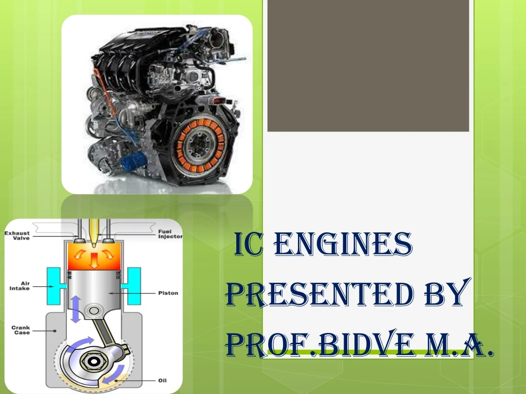
IC ENGINES Presented by Prof.Bidve M.A.
CONTENTS: • INTRODUCTION • HISTORY • IC ENGINE COMPONENTS • 4 STROKES SI ENGINE • COMPRESSION IGNITION ENGINE • 4 STROKE CI ENGINE
Introduction: • Heat engine : It can be defined as any engine that converts thermal energy to mechanical work output. Examples of heat engines include: steam engine, diesel engine, and gasoline (petrol) engine. • On the basis of how thermal energy is being delivered to working fluid of the heat engine, heat engine can be classified as an internal combustion engine and external combustion engine.
Internal combustion engines may be classified as : • Spark Ignition engines. • Compression Ignition engines. • Spark ignition engine (SI engine): An engine in which the combustion process in each cycle is started by use of an external spark. • Compression ignition engine (CI engine): An engine in which the combustion process starts when the air-fuel mixture self ignites due to high temperature in the combustion chamber caused by high compression. • Spark ignition and Compression Ignition engine operate on either a four stroke cycle or a two stroke cycle.
History: • Although various forms of internal combustion engines were developed before the 19th century, their use was hindered until the commercial drilling and production of petroleum began in the mid-1850s. By the late 19th century, engineering advances led to their widespread adoption in a variety of applications.
Internal combustion Engine Components: I.C. Engine components shown in above figures • Cylinder : • Head : • Crankshaft • Connecting rod :. • Piston rings: • combustion chamber:
Camshaft : • Push rods : • Crankcase : • Carburetor : • Spark plug :
I.C. Engine components apart from components shown in the figure: • Exhaust System: • Flywheel : • Fuel Injector: • Glow Plug: • Starter:
Four strokes of SI Engine Cycle : • Suction/Intake stroke: Intake of air fuel mixture in cylinder through intake manifold. • The piston travel from TDC to BDC with the intake valve open and exhaust valve closed. • This creates an increasing volume in the combustion chamber, which in turns creates a vacuum. • The resulting pressure differential through the intake system from atmospheric pressure on the outside to the vacuum on the inside causes air to be pushed into the cylinder. • As the air passes through the intake system fuel is added to it in the desired amount by means of fuel injectors or a carburetor.
Compression stroke: When the piston reaches BDC, the intake valve closes and the piston travels back to TDC with all valves closed. • This compresses air fuel mixture, raising both the pressure and temperature in the cylinder. • Near the end of the compression stroke the spark plug is fired and the combustion is initiated.
I am grateful to Mr. Bidve Sir for his valuable guidance and assessment.