Download
1 / 220
2.22k likes | 2.5k Views
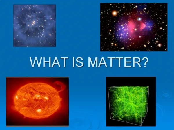
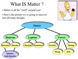
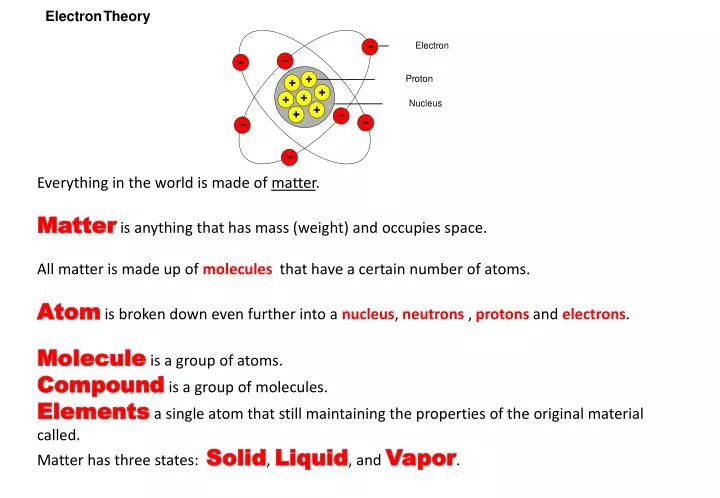
Everything in the world is made of matter . Matter is anything that has mass (weight) and occupies space. All matter is made up of molecules that have a certain number of atoms. Atom is broken down even further into a nucleus , neutrons , protons and electrons .

E N D
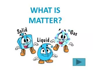
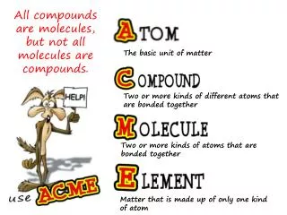
Everything in the world is made of matter. Matter is anything that has mass (weight) and occupies space. All matter is made up of moleculesthat have a certain number of atoms. Atomis broken down even further into a nucleus, neutrons , protons and electrons. Moleculeis a group of atoms. Compound is a group of molecules. Elementsa single atom that still maintaining the properties of the original material called. Matter has three states: Solid, Liquid, and Vapor.
MOLECULE A single molecule of water (H2O) which is made up of two hydrogen atoms and one oxygen atom. Not all materials are made up of molecules. Copper, for example, is made up of a single copper atom.
THE ATOM A single atom consists of three basic components: a proton, a neutron, and an electron. Within the atom there is a Nucleus. The Nucleus contains the protons and neutrons. Orbiting around the nucleus are the electrons.
ATOM CONSTRUCTION An atom is similar to a miniature solar system. As the sun is in the center of the solar system, so is the nucleus is in the center of the atom. Protons and neutrons are contained within the nucleus. Electrons orbit around the nucleus, which would be similar to planets orbiting around the sun.
NUCLEUS The Nucleus is located in the center of the atom (shown in red). The Nucleus contains the protons and neutrons. Orbiting around the nucleus are the electrons.
PROTONS Protons are located within the nucleus of the atom (shown in blue) . Protons are positively (+) charged. NEUTRONS Neutrons add atomic weight to an atom (shown in green).Neutrons have no electrical charge. ELECTRONS Electrons orbit around the nucleus of the atom (shown in yellow).Electrons are negatively (-) charged.
Normally electrons are prevented from being pulled into the atom by the forward momentum of their rotation. Electrons are also prevented from flying away because of the magnetic attraction of the protons inside the nucleus, the same type of force that keeps the planets orbiting around the sun.
ELECTRICAL CHARGES Remember: Unlike charges attract Like charges, repel Atoms always try to remain electrically balanced.
BALANCED ATOMS Atoms normally have an equal number of electrons and protons. The negative charge of the electrons will cancel the positive charge of the protons, thus balancing the charge of the atom. This cancellation of charges creates a natural attraction or bonding
ION PARTICLES When an atom loses or gains an electron, an imbalance occurs. The atom becomes either a positively or negatively charged particle called an ION. IONs will take or release an electron to become balanced again, this process is responsible for electron flow ( electricity ).
ION CHARGE A positive (+) ION has one less electron than it has protons. A negative (-) ION has one more electron than it has protons. The positive ION attracts a negative ION to become balanced.
ELECTRON ORBITS Electrons rotate around the atom at different orbits called Rings, Orbits, or Shells. BOUND ELECTRONS orbit the nucleus on the inner rings. Bound electrons have a strong magnetic attraction to the nucleus. FREE ELECTRONS orbit on the outermost ring which is known as the VALANCE RING.
FREE ELECTRONS Only the FREE ELECTRONS in the outermost shell (Valance Ring) are free to move from atom to atom. This movement is called ELECTRON FLOW. Because of their distance from the nucleus, free electrons have a weak magnetic attraction. Since this attraction is not strong , the electrons move easily from atom to atom.
INSULATORS An INSULATOR is any material that inhibits (stops) the flow of electrons (electricity). An insulator is any material with 5 to 8 free electrons in the outer ring. A toms with 5 to 8 electrons in the outer ring are held (bound) tightly to the atom, and make no room for more electrons. Insulator material includes glass, rubber, and plastic.
CONDUCTORS A CONDUCTOR is any material that easily allows electrons (electricity) to flow. A CONDUCTOR has 1 to 3 free electrons in the outer ring. Because atoms with 1 to 3 electrons in the outer ring are held loosely to the atom, they can easily move to another atom or make room for more electrons. Conductor material includes copper and gold.
SEMICONDUCTORS Any material with exactly 4 free electrons in the outer orbit is called SEMICONDUCTORS. A semiconductor is neither a conductor or insulator. semiconductor material includes carbon, silicon, and germanium. These materials are be used in the manufacturer of diodes, transistors, and integrated circuit chips.
Two Current Flow theories exist. The first is: ELECTRON THEORY The Electron Theory states that current flows from NEGATIVEto POSITIVE. Electrons movefrom atom to atom as they move through the conductor towards positive.
The second Current Flow theory is: CONVENTIONAL THEORY Conventional theory, also known as HOLE THEORY, states that current flows from POSITIVE to NEGATIVE. Protons or the lack of electrons (the holes) moves towards the negative. (Current flow direction in Hole Theory is the opposite of that in Electron Theory) .
VOLTAGE Voltage is the electrical force that moves electrons through a conductor. Voltage is electrical pressure also known as EMF (Electro Motive Force) that pushes electrons. The greater the difference in electrical potential push (difference between positive and negative), the greater the voltage force
Voltmeter The instrument used to measure voltage, difference potential or electromotive force is called voltmeter. A voltmeter is wired in parallel with the circuit to measure voltage. Safety instructions for measuring voltage: 1. choose a suitable voltmeter, each voltmeter is designed witha limit of voltage measurement. 2. Be sure that the connecting of positive terminal (+) and negative terminal (-) of voltmeter are correct.
The Voltmeter measures electrical pressure difference between two points being measured. Voltage can exist between two points without electron flow. Voltage is measured in units called VOLTS. Voltage measurements can use different value prefixes such as millivolt, volt, Kilovolt, and Megavolt.
CURRENT (AMPERES) CURRENT is the quantity or flow rate of electrons moving past a point within one second. Current flow is also known as amperage, or amps for short. Higher voltage will produce higher current flow, and lower voltage will produce lower current flow.
Ammeter is the instrument used to measure current. Safety instructions for current measurement: 1. choose a suitable ammeter, since each ammeter has different limit of current measurement. 2. Be sure that the connection to positive terminal (+) and negative terminal (-) of ammeter are correct. 3. Do not directly connect ammeter terminals to dry cell terminals. Since it can damage the meter.
Ammeters are placed in series (inline) to count the electrons passing through it. Current is measured in units called Amperes or AMP Amperage measurements can use different value prefixes, such as micro amp, milliamp and Amp.
AFFECTS OF CURRENT FLOW Two common effects of current flow are Heat Generation – Electromagnetism HEAT: When current flows, heat will be generated. The higher the current flow the greater the heat generated. An example would be a light bulb. ELECTROMAGNETISM: When current flows, a small magnetic field is created. The higher the current flow, the strongerthe magnetic field. An example: Electromagnetism principles are used in alternators, ignition systems, and other electronic devices.
RESISTANCE Resistance is the force that reduces or stops the flow of electrons. It opposes voltage. Higher resistance will decrease the flow of electrons and lower resistance will allow more electrons to flow.
Ohmmeteris the instrument used to measure resistance. Multi meter is a meter combines the functions of ammeter, voltmeter and ohmmeter. Steps for resistance measurement: Turn the face dial to a position for required measuring, resistance, then touch both of terminals of multi meter (see figure 1) and adjust the meter range to 0 Ω. Touch both of terminals of meter to a resistance and take the reading (see figure 2).
An OHMMETERmeasures the resistance of an electrical circuit or component. No voltage can be applied while the ohmmeter is connected, or damage to the meter will occur. RESISTANCE UNITS Resistance is measured in units called OHMS. Resistance measurements can use different value prefixes, such as Kilo ohm and Mega ohms.
RESISTANCE FACTORS Various factors can affect the resistance. These include: :LENGTH The longer the conductor, the higher the resistance. DIAMETER : The narrower the conductor, the higher the resistance. TEMPERATURE: Depending on the material, most will increase resistance as temperature increases. PHYSICAL CONDITION (DAMAGE) Damage to the material. Any damage will increase resistance. TYPE of MATERIAL Various materials have a wide range of resistances.
There are two basic types of Electricity classifications: STATIC ELECTRICITY is electricity that is standing still. Voltage potential with NO electron flow. DYNAMIC ELECTRICITY is electricity that is in motion. Voltage potential WITH electron flow. Twotypes of Dynamic electricity exist: Direct Current (DC) Electron Flow is in only one direction. Alternating Current (AC) Electron flow alternates and flows in both directions (back and forth).
STATIC ELECTRICITY : Voltage potential with NO electron flow. Example: By rubbing a silk cloth on a glass rod, you physically remove electrons from the glass rod and place them on the cloth. The cloth now has a surplus of electrons (negatively charged), and the rod now has a deficiency of electrons (positively charged).
DYNAMIC ELECTRICITY is electricity in motion, meaning you have electrons flowing, in other words voltage potential WITH electron flow. Two types of dynamic electricity exists: Direct Current (DC) Alternating Current (AC)
DIRECT CURRENT (DC) Electricity with electrons flowing in only one direction is called Direct Current or DC. DC electrical systems are used in cars.
ALTERNATING CURRENT (AC) Electricity with electrons flowing back and forth, negative -positive- negative, is called Alternating Current, or AC. The electrical appliances in your home use AC power.
SOURCES OF ELECTRICITY Electricity can be created by several means: Friction creates static electricity. Heat can act upon a device called a thermo couple to create DC. Light applied to photoelectric materials will produce DC electricity. Pressure applied to a piezoelectric material produce DC electricity. Chemical Action – battery produce DC electricity. – Alternator produce AC electricity.magnetic action
AN ELECTRICAL CIRCUIT The circuit shown below has a power source, fuse, switch, two lamps and wires connecting each into a loop or circle.
ELECTRICAL CIRCUIT REQUIREMENTS A complete Electrical Circuit is required in order to make electricity practical. Electrons must flow from and return to the power source. There are three different circuit types, all require the same basic components: 1. Power Source is needed to supply the flow of electrons (electricity). 2. Protection Device prevents damage to the circuit. 3. Load Device converts the electricity into work. 4. Control Device allows the user control to turn the circuit on or off 5. Conductors provide an electrical path to and from the power source.
BASIC CIRCUIT CONSTRUCTION 1. Power Source (Battery, Alternator, Generator, etc.) 2. Protection Device (Fuse, Fusible Link, or Circuit Breaker) 3. Load Device (Lamp, Motor, Winding, Resistor, etc.) 4. Control (Switch, Relay, or Transistor) 5. Conductors (A Return Path, Wiring to Ground)
LOADS Any device such as a lamp or horn that consumes electricity is called a load. In an electrical circuit, all loads are regarded as resistance. Loads with high resistance cause less current to flow while those with lower resistance allow high current rates to flow.
Ohm’s Law V = IR The voltage change [V](volts) across any resistive load is equal to the product of the current[I](amps) and the resistance[R](Ohms).
WHAT IS OHM'S LAW? A simple relationship exists between voltage, current, and resistance in electrical circuits. OHM'S LAW Ohm's Law says: The current in a circuit is directly proportional to the applied voltage and inversely proportional to the amount of resistance. CURRENT is affected by either voltage or resistance. VOLTAGEis not affected by either current or resistance. RESISTANCE is not affected by either voltage or current.
OHM'S LAW FORMULA E = I R Voltage = Current x Resistance E Voltageapplied to the circuit, in volts (V) I Current flowing in the circuit, in amperes (A) R Resistance in the circuit, in ohms
Example 1 – Instructor Example R = 12 ohms 120 V i = ? Current I = V/R = 120 V/12 Ohms = 10 amps
Example 2 – Student Example R = 24 Ohms 240 V I = ? I =
APPLICATIONS OF OHM'S LAW In the following circuit, assume that resistance R is 2 and voltage V that is applied to it is 12 V. Then, currentI flowing in the circuit can be determined as follows:
APPLICATIONS OF OHM'S LAW V = I x R In the following circuit, assume that resistance R is 4 ohms. The voltageV that is necessary to permit a current I of 3 A to pass through the resistance can be determined as follows:
APPLICATIONS OF OHM'S LAW In the following circuit, assume that a voltage V of 12 V is applied to the circuit and current I of 4 A flows in it. Then, the resistance value R of the resistance or load can be determined as follows:
Kirchhoff’s Laws • Voltage Law:The sum of the voltage rises around a closed loop in a circuit must equal the sum of the voltage drops. • Current Law:The sum of all currents into a junction (node) must equal the sum of all currents flowing away from the junction.
Resistors in Series Applying Kirchhoff’s voltage law gives us: V = IR1 + I R2 + IR3