Download
1 / 112
1.2k likes | 1.61k Views
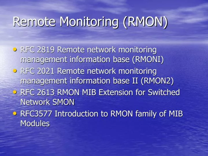
Remote Monitoring (RMON). RFC 2819 Remote network monitoring management information base (RMONI) RFC 2021 Remote network monitoring management information base II (RMON2) RFC 2613 RMON MIB Extension for Switched Network SMON RFC3577 Introduction to RMON family of MIB Modules.

E N D
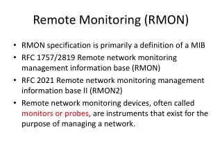
Remote Monitoring (RMON) • RFC 2819 Remote network monitoring management information base (RMONI) • RFC 2021 Remote network monitoring management information base II (RMON2) • RFC 2613 RMON MIB Extension for Switched Network SMON • RFC3577 Introduction to RMON family of MIB Modules
Goals (RFC2819) (1) • Offline Operation • An attempt to lower communications costs (especially when communicating over a WAN or dialup link), or by accident as network failures affect the communications between the management station and the probe. • MIB allows a probe to be configured to perform diagnostics and to collect statistics continuously,
Goals (RFC2819) (2) • Proactive Monitoring • It is potentially helpful to run diagnostics and to log network performance. • It can notify the management station of the failure and can store historical statistical information about the failure. • This historical information can be played back by the management station in an attempt to perform further diagnosis into the cause of the problem.
Goals (RFC2819) (3) • Problem Detection and Reporting • The monitor can be configured to recognize conditions, most notably error conditions, and continuously to check for them. • When one of these conditions occurs, the event may be logged, and management stations may be notified in a number of ways.
Goals (RFC2819) (4) • Value Added Data • The remote network monitoring device has the opportunity to add significant value to the data it collects. • For instance, by highlighting those hosts on the network that generate the most traffic or errors, the probe can give the management station precisely the information it needs to solve a class of problems.
Goals (RFC2819) (5) • Multiple Managers • Environments with multiple management stations are common, the remote network monitoring device has to deal with more than own management station, potentially using its resources concurrently.
Control of Remote Monitor Devices (1) • Configuration • Each MIB group consists of one or more control tables and data tables • Control table – read/write contains parameters that describe the data in data table • Data table – read only contains information that is defined by control table • Action invocation • Use SET operation to issue a command • RMON MIB defines objects to be represented several commands
Control of Remote Monitor Devices (2) • Modifying Parameters • First, invalidate the control entry, causing its deletion and the deletion of any associated data entries • Then, create a new control entry with the proper parameters. • Start Process • Some objects in this MIB provide a mechanism to execute an action on the remote monitoring device. • These objects may execute an action as a result of a change in the state of the object.
Multiple Manager - Problems • Potential conflicts • Two or more management stations wish to simultaneously use resources that together would exceed the capability of the device. • A management station uses a significant amount of resources for a long period of time. • A management station uses resources and then crashes, forgetting to free the resources so others may use them
Multiple Manager – Solution • Ownership label is used for a particular row of the table • A management station may recognize resources its owns and no longer need • A network operator can identify and negotiate the management station to free the resources • A network operator may have the authority unilaterally to free resources another network operator has reserved • If a management station experiences a reinitialization , it can recognize resources it had reserved in the past and free those it no longer needs
Ownership concept • Ownership label contains one or more of the following: • IP address, management station name, network manager’s name, location or phone number • However, the ownership label does not act as a password or access-control mechanism • Therefore, a row can be read-write by the management station who does not own the row
Note (1) • Default functionality • The resources are intended to be long-lived process should be set the relevant owner object to a string starting with 'monitor'. • Indiscriminate modification of the monitor-owned configuration by network management stations is discouraged. • In fact, a network management station should only modify these objects under the direction of the administrator of the probe.
Note (2) • When a network management station wishes to utilize a function in a monitor, it is encouraged to first scan the control table of that function to find an instance with similar parameters to share. • If a management station decides to share an instance owned by another management station, it should understand that the management station that owns the instance may indiscriminately modify or delete it.
Row Addition for Multiple Manager • When more than one manager simultaneously attempts to create the same conceptual row, only the first can succeed. The others will receive an error • When a manager wishes to create a new control entry, it needs to choose an index for that row. • Examples of schemes to choose index values include random selection or scanning the control table looking for the first unused index. • If the index is in use, agent sends an error
RMON Row Addition • If a management attempts to create a new row and the index object value does not exist, the row is created with a status of createRequest(2) • After completing the create operation, the agent sets the status object value to underCreation (3) • After management station is finished creating all of the rows that it desires for its configuration, the management station sets the status object value tovalid (1) • It an attempt is made to create a new row and the row already exists (duplicate index) an error will be returned
Good Packets • RFC 2819 • Good packets are error-free packets that have a valid frame length. • For example, on Ethernet, good packets are error-free packets that are between 64 octets long and 1518 octets long.
Bad Packets • Bad packets are packets that have proper framing and are therefore recognized as packets, but contain errors within the packet or have an invalid length. • For example, on Ethernet, bad packets have a valid preamble and SFD, but have a bad CRC, or are either shorter
The RMON MIB • RMON (v1) MIB is incorporated into MIB-II with a subtree identifier of 16 (10 groups) • statistics: maintains low-level utilization and error statistics for each subnetwork monitored by the agent • History: record periodic statiscal samples from information available in the statistic group
RMON MIB Group • alarm: allow the management console user to set a sampling interval and alarm threshold for any counter or integer recorded by the RMON probe • host:contains counter for various types of traffic to and from hosts attached to the subnetwork • hostTopN: contains sorted host statistics that report that top a list based on some parameter in the host table
matrix: show error and utilization information in matrix form • filter:allow the monitor to observe packet that match a filter • (Packet) capture: governs how data is sent to a management console • event: gives a table of all events generated by RMON probe • tokenRing:maintains statistics and configuration information for token ring subnetworks
Important note 1 • All groups in the RMON MIB are optional but there are some dependencies • The alarm group require the implementation of the event group • The hostTopN group requires the implementation of the host group • The packet capture group require the implementation of the filter group
Important note 2 • Collection of traffic statistics for one or more subnetworks • statistics, history, host, hostTopN, matrix, tokenRing • Various alarm conditions and filtering with user-defined • alarm, filter, capture, event
Statistics Group (1) • Fig 8-6
Statistics Group (2) • Table 8.2
Statistics Group (4) • The statistics group provides useful information about the load and overall health of the subnetwork • Various error conditions are counted such as CRC or alignment error, collision, undersized and oversized packets
History Group • The history group is used to define sampling functions for one or more of the interfaces of the monitor • 2 tables • historyControltable – specify the interface and detail of sampling function • etherHistorytable – record data
historyControlTable • historyControlIndex: index of entry which is the same number as used in etherhistoryTable • historyControlDataSource: identify interface to be sampled • historyControlBucketsRequested: the requested number of discrete sampling interval, a default value is 50 • historyControlBucketsGranted: the actual number of discrete sampling interval • historyControlInterval: interval in second, maximum is 3600 (1 hour) ,default value is 1800
Sampling scheme • Consider by historyControlBucketGranted and historyControlInterval • Ex. Use the default value of both • the monitor would take a sample once every 1800 seconds ( 30 min) each sample is stored in a row of etherHistoryTable • The most 50 rows are retained
Utilization • It calculates on the two counters :ehterStatsOctets and etherStatsPkts • Utilization=100% x [(Packets x (96+64)))+(Ocetsx8)/interval x 107] • 64 bit – preamble • 96 bit – interframe gap • Assume that interface data rate is 10Mbps
Host Group • To gather statistics about specific hosts on the LAN by observing the source and destination MAC addresses in good packets • Consists of 3 tables: • one control table (HostControlTable) • two data tables (hostTable,hostTimeTable) same information but index differently
hostControlTable • hostControlIndex: • identify a row in the hostControlTable ,refering to a unique interface of the monitor • hostControlDatasource: • identify the interface (the source of the data) • hostControlTablesize: • the number of rows in hostTable (hostTimeTable) • hostControlLastDeleteTime: the last time that an entry (hostTable) was deleted
A simple RMON configuration • Fig8.10
hostTable • hostAddress: MAC address of this host • hostCreationOrder: an index that defines the relative ordering of the creation time of hosts (index takes on a value 1-N) • hostIndex : the same number as hostControlIndex
hostTopN Group (1) • To maintain statistics about the set of hosts on one subnetwork that top a list based on some parameters • Statistics that are generated for this group are derived from data in the host group • The set of statistics for one object collected during one sampling interval is referred as report
hostTopN Group (2) • Each report contains the results for only one variable • The variable represents amount of change in a host group object over the sampling interval • So, the report lists the hosts on a particular subnetwork with the greatest rate of change in a particular variable
hostTopNControlTable(1) • hostTopNControlIndex : • identify row in hostTopNControlTable,defining one top-N report for one interface • hostTopNHostIndex: • match the value of hostControlIndex ,specifying a particular subnetwork • hostTopNRateBase: • specify one of seven variables from hostTable
hostTopNControlTable(2) • Variable in hostTopNRate • INTEGER { hostTopNInPkts (1), hostTopNOutPkts (2), hostTopNInOctets (3), hostTopNOutOctets (4), hostTopNOutErrors (5), hostTopNOutBroadcastPkts (6), hostTopNOutMulticastPkt (7), }
hostTopNControlTable(3) • hostTopNTimeRemaining: • time left during report currently being collected • hostTopNDuration: • sampling interval • hostTopNRequestedSize: • maximum number of requested hosts for the top-N report • hostTopNGrantedSize: • maximum number of hosts for the top-N report • hostTopNStartTime: • the last start time