Download
1 / 61
610 likes | 612 Views
ENT265 Microcontroller & Interfaces. Chapter 0 & 1 Introduction to Computer Architecture. 28 Dec 2009. Basic Computer Architecture. CPU (Central Processing Unit) Memory Input/Output. Buses. I/O. CPU. Memory. Inside the computer. Internal Organization of a Computer.

E N D
ENT265Microcontroller & Interfaces Chapter 0 & 1 Introduction to Computer Architecture 28 Dec 2009
Basic Computer Architecture • CPU (Central Processing Unit) • Memory • Input/Output Buses I/O CPU Memory
CPU Function: To execute (process) information stored in memory • I/O Devices: Communicating with the real world • CPU connected to memory and I/O through strips of wire called bus
Microprocessor System Contrasted With Microcontroller System
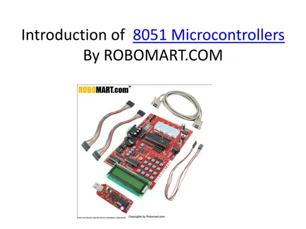
PIC Program ROM • Also known as Code ROM • Used for storing programs. Several versions of ROM: • UV-EPROM • Flash • One-Time-Programmable (OTP)
PIC RAM • Space for data storage • Has two component: • General Purpose Register (GPR) • Scratch pad • Special Function Register (SFR) • Module function usage
PIC EEPROM (Optional) • To store critical data that does not need to be change very often
The CPU • Purpose: The controlling element in a computer system that performs data transfers, integer arithmetic and logic, and input/output operations. • Sizes: 4-bits to 64-bits • Speeds: up to 4 GHz • A byte is 8-bits • Memory is addressed by byte • RISC vs. CISC
CPU Task • Executes instructions from the memory system. • A program is a collection of instructions stored sequentially in the memory. • A program is the computer’s software. • The stored program concept makes the computer fast and powerful.
Data Transfer Operations • Most of a CPUs time is spent transferring data. • Data transfers include: instruction fetches, transfers between memory and registers, transfers between registers and I/O. • Transfers occur though the data bus.
Arithmetic and Logic Operations • The CPU performs arithmetic on integers using addition, subtraction, multiplication, and division (some microcontrollers do not divide). • Logic operations include AND, OR (inclusive and exclusive), NOT, and shift/rotate.
Decisions • The CPU makes decisions based upon numeric facts to control the flow of a program. • Zero—Not Zero, Positive—Negative, Carry—No Carry • Decisions modify the flow of a program • Flow control allows tasks to be repeated or skipped.
Memory • Memory in a computer system is normally numbered in bytes. • Memory is accessed by bytes using a memory address (address bus) numbered from memory location 00000000. • Memory addresses are expressed in the hexadecimal numbering system (radix 16). • Memory data flow through the data bus.
Data Bus • The data bus is 4-, 8-, 16-, 32-, or 64-bits in width in modern computers. • The size of the CPU and its data bus are the same or in some cases the data bus may be twice as wide as the CPU size. • A 16-bit computer has a 16-bit data bus. • The Pentium 4 is a 32-bit computer with a 64-bit data bus.
Address Bus • The address bus selects a memory location or an I/O device • The size (number of bits) of the address bus determines the maximum memory size. • An 8-bit address can address 256 bytes of memory (28). • 1K = 1024 and requires a 10-bit address • 1M = 1024 * 1024 and requires a 20-bit address • 1G = 1M * 1024 and requires a 30-bit address • 1T = 1G * 1024 and requires a 40-bit address
Control Bus • The control bus controls memory and I/O. • The control bus contains two main signals that originate from the CPU. • The #RD signal causes a read operation. • The #WR signal causes a write operation. • Some CPUs also contain a signal that selects memory or I/O called M/#IO.
ROM • A ROM is a nonvolatile memory that is used to store programs and static data • The ROM is usually either an EPROM or an EEPROM memory. • The EPROM is erased using an ultraviolet lamp. • The EEPROM is erased electrically • In either device, memory does not change when power is removed from the system.
RAM • The RAM is the read/write memory in a system that stored dynamic data and will not retain data without power. • RAM is available as either SRAM or DRAM. • SRAM stores data as long as power is applied. • DRAM must be refreshed because it only stores data for a few milliseconds. • Large memory system usually use DRAM and small memory systems usually use SRAM.
I/O • The I/O in a computer allows the CPU and its program to communicate to humans and machines. • A input device inputs data to the CPU and examples include keyboards and switches. • An output device accepts data from the CPU and examples include printers, indicators, and so forth. • I/O data is often 8-bits in width.
Internal Architecture: von-Neumann Architecture The CPU can either read an instruction or read/write data from/to the memory. Both cannot occur at the same time
Internal Architecture: Harvard Architecture CPU can read an instruction and perform a data memory access at the same time
INSTRUCTION SET RISC (Reduced Instruction Set Computer) i.e. PIC Microcontroller CISC (Complex Instruction Set Computer) i.e. Intel 8085
Number Systems • Numbers systems used with computers are usually binary and hexadecimal. • Positional notation is often used to convert a number from any number system to decimal. Power 22 21 20 2-1 2-2 2-3 Weight 4 2 1 .5 .25 .125 Number 1 1 0 . 1 0 1 Numeric Value 4 + 2 + 0 + .5 + 0 + .125 = 6.625
Power 161 160 16-1 Weight 16 1 .0625 Number 6 A . C Number Value 96 + 10 + .75 = 106.75
Whole Number Conversion from Decimal • The key is division by the radix or number base. • The algorithm: 1. Divide the decimal number by the radix (number base). 2. Save the remainder (first remainder is the least significant digit). 3. Repeat steps 1 and 2 until the quotient is zero.
To convert 10 decimal to binary 2) 10 remainder = 0 2) 5 remainder = 1 2) 2 remainder = 0 2) 1 remainder = 1 result = 1010 0
To convert 106 decimal to hexadecimal 16) 109 remainder = 13 (D) 16) 6 remainder = 6result = 6D 0
Converting fractions from Decimal • The key is multiplication by the radix • The Algorithm 1. Multiply the decimal fraction by the radix (number base). 2. Save the whole number portion of the result (even if zero) as a digit. Note that the first result is written immediately to the right of the radix point. 3. Repeat steps 1 and 2, using the fractional part of step 2 until the fractional part is zero.
Converting 0.125 to binary .125 x 2 0.25 digit is 0 .25 x 2 0.5 digit is 0 .5 x 2 1.0 digit is 1 result = 0.0012
Converting 0.046875 to hexadecimal .046875 x 16 0.75 digit is 0 .75 x 16 12.0 digit is 12(C) result = 0.0C16
Binary Coded Hexadecimal (BCH) • Hexadecimal number are converted to binary in groups of 4-digit binary number by inspection. • For example to convert 2A hexadecimal to binary convert to 2 to 0010 and the A to 1010 as follows: 2A = 0010 1010
Binary to BCH 101001001 = 0001 0100 1001 = 1 4 9
Complements • Two types of complements exist: The radix complement and the radix minus ones complement. • The radix complement minus 1 is the 1’s complement for binary and is created by subtracting each digit from 1. 1111 1111 – 0100 1100 1011 0011
Radix Complement • The radix complement is the two complement in binary and is created by forming the 1’s complement and adding a 1 to the 1’s complement 1111 1111 – 0100 1000 1011 0111 (one’s complement) + 1 1011 1000 (two’s complement)
15 15 15 – 3 4 5 C B A (fifteen’s complement) + 1 C B B (sixteen’s complement)
ASCII Data • ASCII (American Standard Code for Information Interchange) is the code most often used for alphanumeric data. • The ASCII code is a 7-bit code and the extended ASCII code is an 8-bit code.
Storing ASCII Code in an Assembly Language Program DB 'B' DB 'r' DB 'e' DB 'y' DB 0x00 DB 'Brey', 0 DATA "Brey", 0 DATA "Barry", 0