Download
1 / 32
350 likes | 667 Views
X-ray imaging based on small-angle X-ray scattering using spatial coherence of parametric X-ray radiation. Yasushi HAYAKAWA. Laboratory for Electron Beam Research and Application (LEBRA), Institute of Quantum Science, Nihon University RREPS-13 (23-27 Sep. 2013, Sevan, Armenia).

E N D
X-ray imaging based on small-angle X-ray scattering using spatial coherence of parametric X-ray radiation Yasushi HAYAKAWA Laboratory for Electron Beam Research and Application (LEBRA), Institute of Quantum Science, Nihon University RREPS-13 (23-27 Sep. 2013, Sevan, Armenia)
Collaborators Y. Hayakawa1, K. Hayakawa1, M. Inagaki1, T. Kaneda2, K. Nakao1, K. Nogami1, T. Sakae2, T. Sakai1, I. Sato3, Y. Takahashi4, T. Tanaka1 1Laboratory for Electron Beam Research and Application (LEBRA), Institute of Quantum Science, Nihon University 2Nihon University School of Dentistry at Matsudo 3Advanced Research Institute for the Science and Humanities, Nihon University 4Institute of Materials Structure Science, High Energy Accelerator Research Organization (KEK)
Outline • LEBRA facility at Nihon University& the LEBRA-PXR source • Diffraction-enhanced imaging (DEI) using the LEBRA-PXR source • Imaging technique based on small-angle X-ray scattering (SAXS) • Summary & prospects
Nihon University Funabashi, Chiba
LEBRA facility LEBRA: Laboratory for Electron Beam Research & Application Tunable light-source facility based on a conventional S-band electron linac elctron energy: 125MeV(max.), 100MeV(typ.) average current : 5μA (max.), 1 – 3 μA(typ.)
klystron X-ray beam Tunable light source facility THz-CSR (coherent synchrotron radiation) PXR (parametric X-ray radiation) source : 5 - 34keV infrared FEL (free electron laser) : 1μm – 6μm
PXR FEL Beamlines (PXR & FEL)
Double crystal system for PXR To actualize an X-ray source based on PXR, a double crystal system was proposed and developed. The 1st crystal is a target of electron beam and a radiator of PXR. The 2nd crystal is a reflector to transport PXR through a fixed exit port penetrating 2m shield wall.
2nd crystal (reflector) Q magnet e-beam 1st crystal (radiator) Radiator of the PXR source PXR radiator: 0.2mm thick Si perfect crystal wafer reflector: 5mm thick Si perfect crystal plate crystal plane: Si(111) for 5 – 20keV Si(220) for 6.5 – 34keV
Status of LEBRA-PXR source electron energy 100 MeV accelerating frequency 2856 MHz bunch length~3.5 ps macropulse duration 4 - 10 s macropulse beam current ~130 mA repetition rate 2 – 5 pps average beam current 1 - 3 A electron beam size 0.5 – 1mm in dia. X-ray energy range Si(111): 5 – 20 keV Si(220): 6.5 – 34 keV irradiation field 100 mm in dia. total photon rate ≥ 107 /s @17.5keV
Feature of LEBRA-PXR source • X-ray energy does not depend on the electron energy but on the crystal arrangement (Bragg angle). • Wide and continuous tunability • Si(111): 5 -20keV, Si(220): 6.5 -34keV • Cone-beam depending on 1/γIrradiation field of 100mm in diameter at the exit window(distance from the source to the window: 7.3m) • PXR beam has energy dispersion (spatial chirp) along the horizontal direction.
7.3m X-ray imaging (absorption contrast) diameter: 100mm exit window PXR radiator: Si(111) PXR energy: 17.5keV (center) e-beam: 2.6uA (average) sample: calculator detector: imaging plate (IP) exposure: 10s PXR radiator: Si(111) PXR energy: 17.5keV (center) e-beam: 2.6uA (average) sample: human tooth detector: flat panel detector (FPD)
Cu (K-edge: 8.981keV) Zn (K-edge: 9.661keV) Spatial chirp of PXR beam slight & continuous wavelength-shift (spatial chirp) narrow local bandwidth (several eV) Wave front of PXR is different from both plane wave and spherical wave.
Typical result of DXAFS experiment “Spatial chirp” can be used for dispersive X-ray fine structure analysis. sample SrTiO3 (white pigments) measurement time 30min detector: Imaging plate EXAFS oscillation absorption spectrum radial distribution function
PXR source analyzer angle [deg.] (+, -, +) arrangement Using a 3rd analyzer crystal in the (+,-,+) arrangement, the whole of a PXR beam can be diffracted with a narrow angular width despite the cone-beam. (pseudo-plane wave) Bragg case Laue case Bragg angle: larger for longer wavelengths smaller for shorter wavelengths
R. Fitzgerald: Phys. Today 53 (2000) 23 Phase-contrast X-ray imaging interferometer-based technique Si perfect crystal interferometer Talbot interferometer analyzer-based technique DEI: diffraction-enhanced imaging propagation-based technique The narrow diffraction width means that DEI is possible using PXR.
Setup of DEI experiments top view Due to the extension of cone-beam, a wide irradiation field can be obtained without asymmetric analyzer. The distance between the PXR source and the sample is shorter than 10m.
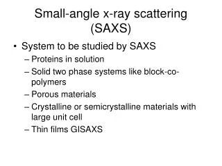
Interaction between X-rays and sample materials heavy material granular material light material refraction (phase shift) absorption (amplitude attenuation) small angle X-ray scattering (SAXS)
Transformation of rocking-curve shapes small-angle scattering: reduction of the peak height (or peak broadening) of the curve refraction: shift of the center of the curve absorption: reduction of the area of the curve The angular resolution for refraction and scattering depends on the diffraction width of the analyzer crystal.
Experiment for demonstration Sample: acrylic rod (3mm in dia.) density: 1.17 g/cm3 styrene-foam rod (6mm in dia.) density: 0.16 g/cm3 polystyrene rod (3mm in dia.) density: 0.986 g/cm3 DEI measurement setup: analyzer: Si(220) 160mm x 35mm x 5mm angular step: 0.4625 μrad image sensor: X-ray CCD (Q.E. @25.5keV ~ 10% ) pixel size: 24μm x 24μm PXR source: radiator-reflector: Si(220)-Si(220) electron energy: 100MeV average beam current: 3μA PXR energy: 25.5keV photon rate: ~ 106 /s /100mm in dia.
Result of DEI measurement The DEI image contrast varies according to the analyzer angle.
Rocking curves at each ROI 13 DEI images were taken by using an X-ray CCD (Q.E. @25.5keV ~ 10%) Each exposure time: 15min θ
absorption-contrast image y x x complex refraction index: n(x,y) = 1 – δ(x,y) + iβ(x,y) δ, β∝ ρ: density Integral with respect to θ Iabs = ∑ I(x,y, θ) ln(Iabs(x,y)/I0) ∝ β(x,y) ∝ ρ(x,y)
phase-gradient image y x x phase-gradient (refraction-contrast) map ∑θ I(x,y, θ)/∑ I(x,y, θ) ∝ ∂δ(x,y) /∂x
phase image y x x phase map δ(x,y) = ∫ ∂δ(x,y) /∂x dx ∝ ρ(x,y)
Visibility contrast due to SAXS effect visibility contrast: I(x,y, θ=0) – I(x,y, θ=2σ)
SAXS-based (visibility-contrast) image x x the contrast is sensitive to the styrene-foam region independently of the density and the shape of the sample.
Small angle X-ray scattering (SAXS) wavelength λ q θ q = | q | = ( 4π / λ ) sin(θ/2) Guinier approximation: Rg : inertial (gyration) radius
Guinier plot exp(-Rg2q2/3) styrene-foam region direct beam region inertial radius Rg ~ 1μm < pixel size (24 μm) q = ( 4π / λ ) sin(θ/2) For more exact estimation, the sample thickness has to be optimized.
Summary • Combining the cone-like divergence and the spatial chirp of PXR allows DEI using a PXR beam in the (+,-,+) arrangement. • X-ray refraction and small-angle X-ray scattering (SAXS) due to sample materials can be measured simultaneously by the DEI method. • DEI experiments using PXR successfully demonstrated that SAXS-based imaging is sensitive to micro structures of sample materials smaller than the pixel size of the image sensor. • PXR beam has a sufficiently high spatial coherence to detect scattering angles in the range of micro-radian.
Prospects for application SAXS based imaging is very sensitive to micro structures of sample materials. expected application: • analysis for material science nano-material, liquid crystal, … • Analysis for bio-chemical science macromolecular, protein, ... • pathological examination tissue fibrosis, ...
Acknowledgements • Nihon University Multidisciplinary Research Grant for 2012 (Sogo: 12-19) • MEXT.KAKENHI (24651105, 24560069) Thank you for your kind attention !!