Download
1 / 23
230 likes | 386 Views
Design and Prototype Test of SCINTILLATING FIBER TRACKER . Supported by 2014 JSA Postdoc Prize. Zhihong Ye Duke University JLab User Group Meeting, 06/03/2014. Original Motivation: The Proton Charged Radius Experiment (PRad) in Hall-B.

E N D
Design and Prototype Test ofSCINTILLATING FIBER TRACKER Supported by 2014 JSA Postdoc Prize Zhihong Ye Duke University JLab User Group Meeting, 06/03/2014
Original Motivation:The Proton Charged Radius Experiment (PRad) in Hall-B • High resolution, large acceptance, hybrid HyCal calorimeter (PbWO4 and Pb-glass) • Measure GEp within Q2 range of 2x10⁻⁴ – 2.0x10⁻² GeV2 (lower than all previous (e,p) experiments) • Simultaneous detection of elastic and Møller electrons • Windowless H2 gas flow target Add a new position detector here • To increase the resolution at the lowest Q2 points, we decied to add a new position detector with additional features: • Thin Not too much space between Vacuum Box Exit and HyCal • Minimum radiation materials Control the background events at a small level. • Allow a hole at the center for the electron beam to go through 2 Spokesperson: A. Gasparian, D. Dutta, H. Gao, M. Khandaker 2
Original Motivation:The Proton Charged Radius Experiment (PRad) in Hall-B • Possible Candidates of Position Detectors (or Tracking Devices): • Drift Chambers (DC) • Provide <100 um position resolution; Thin; Widely used; • No enough time to design, built and test a 1.2 meter x 1.2 meter large DC; • Hard to produce a hole at the center; • GEM current selection • High tracking resolution (<100um) and good timing (~ 10ns); High rate; Insensitive to EM field • UVa (NilangaLiyanage’s group) can produce 120cm x 60cm plates; • A hole can be produced; • Can be ready before the experiment; Readout electronics are available; • Scintillating Fiber Tracker (SFT) as a backup due to the lack of time, man-power and experience • Good position resolution: e.g. 1mm fibers can give as good as ~300um; • Thin, e.g. 1 mm plastic fiber gives only <0.3% radiation length; • Replace Veto-Counter to perform precise time-measurement at the same time • A hole can be easily produced. • And more advantages!
Scintillating Fiber Tracker: Advantages • Scintillating Material: emits visible lights via de-excitation when a charged particle deposits its energy through ionization process; • Scintillating Fiber (SciFi): A core of scintillating materials with one or several layers of thin cladding with lower index of refraction; • Good Time Response: SFT can provide better timing measurement than DC and GEM; • Without Gas Systems: Unlike GEM and DC; • Easy Handling: Easily installed, stored and transported; can be used in vacuum or high EM field; • Easy Analysis: We just need to determine which SciFi is fired (“YES/NO” algorithm). This new SFT can have a wide application in many projects!
Scintillating Fiber Tracker:Previous Developments • Existing similar detectors (since 1990s): • Mainly applied in Medical Imaging (small size): • e.g., Proton Computed Tomography Scanner (FERMILAB-PUB-12-067-E), INFN • D0 in Fermi Lab: 0.84 mm SciFi + Visible Light Photon-Counter (VLPC) • Four concentric cylinders(Nucl. Phy. B 61B (1998) 384-389) • KAOS in Mainz: 200cm wide 50cm long 0.25mm SciFi + Multi-Anode PMT • 200cm x 50cm, only the vertical plane (C. AyerbeGayoso, PhD thesis) by INFN • New detectors under developing: • LHCb: 300cm long 0.25mm round SciFi+ Silicon Photon Multiplier • 250cm x 300cm, 5 super layers, only the vertical plane • COMPASS, HERMES, SONTRAC, etc …
Scintillating Fiber Tracker:Our Design • The new SFT proposed for PRad: • 120cm x 120cm active area • SciFi would be about 1.5m long • X&Y position tracking on electrons • Two perpendicularplanes, each has two layers of SciFi • Time measurement on electrons • replacing veto-counter to reject photons • A hole at the center allowing the beam pipe to go through Detector Frame Photon-Detectors on one side only For 1mm SciFi (300um resolution), ~4800fibers and ~2400output-channels! (If combining two-fibers and reading out signal from one-end) • What we should know before we build: • What type of SciFi? How many layers? • How to assemble the SciFi? • How to mount the SciFi on the supporting structure? • What type of photon-detector? • Silicon Photon Multiplier (SiPM) or Multi-Anode PMT (MaPMT) ? • What Read-Out system? • How to reduce the cost? Two fibers as one readout
Prototype Test Project: https://wiki.jlab.org/pcrewiki/index.php/Prototype_Test The Plan Propose the project Prepare Setup Purchase Samples Test SiPM Test SciFi Purchase & Assemble SciFi Here we are! • The SFT Prototype: • 5 cm x 5 cm active area • 50 (X) and 50 (Y) read-out channels • 200 1.5 meter long SciFi • 100 SiPMs • Mounting Frame and Supporting Struecture Purchase / Make (Detectors, PS, PreAmp) Design Mounting Frame Read-Out System (FastBus, fADC, others?) Test Tracking Performance (with beam?)
Prototype Test Project:The Hall-a Laser Lab shared with SoLID-EC test
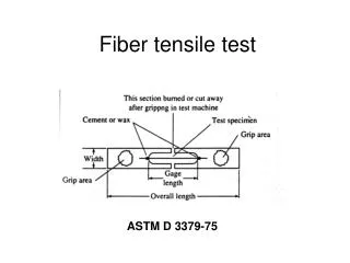
Prototype Test Project:SciFi Test • Selection of SciFi: • Numbers about SciFi claimed by manufactures: • ~8000(?) photons/MeV for each MIP within a 1mm fiber; • ~3.1% Trap-Efficiency for Single-Clad (~5.4% for Multi-Clad); • ~ 3 ns Decay Time; • ~4 m Attenuation Length (for blue light); • Position Resolution: , where D is the diameter of the fiber Single-Clad Multi-Clad Considering the quantum efficiency of photon-detector (<30%), 1-mm SciFi gives <50 p.e. on each end, but it should be much lower in reality . • We look for one type of SciFi that has: Strong Light-Yield, Mechanically Strong, and High Detection Efficiency. • Option 1 ---Square Fiber • Option 2 ---Round Fiber Charged Particle Direction Good: Longer Attenuation Length Bad: Larger Gaps, Poor Trap-Efficiency (position dependence) Good: Smaller Gaps (maximize the detection efficiency), Easier Align&Assembling Bad: Shorter Attenuation Length For our SFT with 150 cm fibers, square fiber may be better.
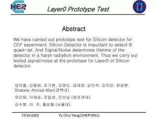
Prototype Test Project:SciFi Test • SciFi Testing Setup: The SciFi being testing: • New Fiber-Samples from Kuraray: • 1, x2 SCSF-78MJ , 1mm, Round, 3meters, Multi-Clad • 2, x2 SCSF-78MSJ , 1mm, Round, 3meters, • mechanics stronger, Single-Clad (30% less light yield) • 3, x2 SCSF-78J, 1mm, Square, 3meters • 4, x2 SCSF-78J, 1.5mm, Square, 3meters • From Hall-D: x8 SCSF-78MJ 1mm, Round, 2 meters Goal: Measuring the Light-Yield and Attenuation Length for different types of SciFi. 3um 2um 1um SciFi Polishing Tools
Prototype Test Project:SciFi Test • SciFi Testing Setup: 1-inch PMT (Hall-C) Scintillator (HallC) Ru106 Radiation Source SciFi We built a 200cm x 20cm Black-Box ! Thank you! Walter Kellner @Hall-C Machine Shop! Mounting Block
Prototype Test Project:SciFi Test • SciFi Testing Setup: Quick check 1mm 78MJ-Round 1mm 78MSJ-Round • Checked the signals with Oscilloscope; • Will take data with DAQ this week; • Hall-D has done many tests with 78MJ which gives ~ 8 p.e.; • ~20 p.e. would be a good number to get high detection efficiency (add two fibers); • The fibers are needed to be polished with better tools (borrowing a polishing-machine from Hall-D). • Hall-D’s experiences and test results can be adopted! ~5 p.e. ~8 p.e. 1.5 mm 78J-Sqaure 1mm 78J-Square ~7 p.e. ~10 p.e.
Prototype Test Project:SciFi Test • Assembling & Mounting: Just a plan. • Carl Zorn and Brian Kross, etc. in the Detector Group have given many suggestions • Will learn from Carlos Ayerbe who built the SFT for KAOS@Mainz: • http://wwwa1.kph.uni-mainz.de/A1/publications/doctor/ayerbe.pdf • Mark Emamian from Duke is helping the Mounting Frame design. The plan is divided into groups Fibers Rohacell Foam Aluminum Frame RohacellFoam+Carbon Fiber Foil Screw Mounting Cookie on each end (Scheme Draw) • Challenge for us– How to avoid the horizontal SciFis to bend down? Optical Glue Solution: Glue them on a plane with Rohacellfoam+carbon fiber foils Problem: Adding more dense materials (potential radiation background)
Prototype Test Project:SiPM Test SiPMAvalanche Photodiode (APD) pixels working in Geiger-mode • Photon Detectors: 1, SiPMs: Silicon Photon Multiplier • Cheap ~$10 per SiPM+~$10 power supply+~$10 Pre-Amp; • Large Gain ~~ x106 ; • Insensitive to magnet field • Need a Pre-Amp Design Hall-D has a very good design • Gain is temperature-depended • Relatively larger dark current; • Radiation damage by the neutron background; • Cross-Talk One photon only fire one pixel (unless cross-talk or dark-current) Hamamatsu MPPC S12572-100P/50P Used in Hall-B & Hall-D for testing We newly purchased Hamamatsu Multi-Pixels Photon Counter (MPPC)
Prototype Test Project:SiPM Test • Photon Detectors: 2, MaPMTs (possible candidate) • More commonly used; • Multi-channels outputs • Much cleaner background; • High radiation tolerance; • Degraded performance in strong magnet field; • Cross Talk • Expensive; • Our Duke group has a 64ch H8500 MaPMT for test • We will borrow a 16ch MaPMT from SBS From Carlos Ayerbe’s thesis
Fiber+SiPM Mounting Block Prototype Test Project:SiPM Test Thank you, Walter Kellner! • SiPM Test Setup: High Precision Power Supply (Hall-D) x2 Low Voltage Power Supplies (Hall-A&-D) Sr90 Black Box (from SimonaMalace) Temperature Sensor 4mm Scin. Strip+SiPM Fan SiPMs with Pre-Amp (Hall-D) SiPMs with Pre-Amp (Stepan@Hall-B) Goal: Understand the performance of the SiPM --- Gain, Noise Level, Stability with Temperature, ADC & TDC spectra.
Prototype Test Project:SiPM Test 1 p.e. 2p.e. • SiPM Test Setup: (Stepan’sSiPMs+Pre-Amp) 3 p.e. 3 p.e. Hamamatsu Measurements (what we expect to see) 2 p.e. 1 p.e. • Not yet seen pretty pattern from scope • More to learn about SiPM • Data taking with DAQ will be proceeded soon;
Prototype Test Project: Read-Out System • Read-Out System of >2400 Output Channels: 1, SiPM (or MaPMT) + FastBus ADC + TDC Requires a large amount of NIM modules and long delay cables 2, SiPM (or MaPMT) + fADC Need >20 fADC & VME64 which are rare and expensive • 3, A “Cheaper” Solution EASiROC for SiPM or MaROC for MaPMT • Developed by OMEGA@IN2P3; • Pre-Amp integrated with adjustable Low/High Gains; • ADC outputs and TDC outputs; • One “OR” logic output for triggering; One “SUM” analog output; • ~$130 for each chip (or <$5 per channel); • Need an additional readout board (“expensive”) 16 OMEGA Test Board (USB readout)
Prototype Test Project: Read-Out System • Read-Out System of >2400 Output Channels: EASIROC (or the new version called CITIROC) 32 ADC Outputs 32ch Inputs with adjustable High/Low Gain 32 TDC Outputs Logic Output SiTCP read-out board designed at KEK (TCP/Ethernet 1Gbps ) • A new MaROC3 with a read-out board (USB port) has been purchased for SoLID-EC test; We will study its performance with SULI students’ help. NIM-based Read-Out Board designed by I. Nakamura (KEK) for J-PAC With EASIROC+SiPM or MaROC+MaPMT, the SFT will be “portable”!
Summary: • SFT provides a great option to improve the PRad experiment and can be applied to many other projects. • Prototype Testing Project is undergoing: • (1) It took a few months to prepare the setup due to very limited resources. • (2) Received and receiving many helps from colleagues in Hall-A/B/C/D, Detector Group, Duke Univ, etc. • (3) We have almost everything set up and will have some serious results very soon. • Near Term goals (not working n full-time): • Test and choose SciFi; • Test SiPM and MaPMT • Design and build the mounting structure • Assembling the 1.2m x 1.2m SFT is challenging but practicable. • Three options of the read-out systems are available. • Highly appreciate your suggestions and helps, and welcome to join. • I hope one day the full size SFT can be built!
Acknowledgement: • I am grateful to receive many helps from: • Hall-A: Alexandre Camsonne, J-P Chen, Jack Segal, etc • Hall-B: Sergey Boyariov, StepanStepanyan, YouriSharabian, etc. • Hall-C: Joe Beaufait, Mark Jones, Walter Kellner, SimonaMalace, Brad Sawatzky, etc • Hall-D: Elton Smith, Yi Qiang, etc • Detector Group: Brian Kross, Wenze Xi, Carl Zorn, etc. • RadCon: Adam Hartberger • Many other colleagues and friends • Special Thanks are given to: • JSA User Board that give me the Postdoc Prize and offer me such a precious opportunity • Hard working Graduate Student: Chao Peng (Duke), Li Ye (Mississippi Statue) • Brad Sawatzky and Yi Qiangwho lend me many instruments and help me to complete the setup • Prof. Haiyan Gao, Yi Qiang and StepanStepanyan who give me many advices to design and • carry out this project. • Prof. Donal Day, Prof. Haiyan Gao and Doug Higimbotham who provide the reference letters. • And the PRad collaboration & SoLID collaboration.
Cost Estimation of the Full-Size SFT: • Each Fiber: 1mm width ( round or square ) is $1 per meter. • for 1.2m x 1.2m, we need roughly 2400 1.5m-long fibers for each plane to cover the gaps. • for x-y two planes, 4800 fibers ~ $7.2 K • Photo-Detector: SiPM module $10 for each channel quoted from Hamamatsu. • Amplifier used in Hall-D: $10 for each channels ( plus Design Fee $???) • Power Supply (~$10 for each channel) • For one-end read-out: 2400 channels x $30 per channel ($72K + engineer design of the Pre-Amp) • Mounting Frame and Supporting Structure ($???) • Connectors + Cables + Tools + Supplies ($???) • ReadOut+DAQ: • From SiPM to raw data: Discriminators, FastBus ADC & TDC (40 cards for each) (or fADC ) • OR: EASIROC --- $100 for 32 channels • + Read-Out Board ( we need to borrow designs and make all by ourselves ~$1500 per board or cheaper) • Total Read-Out: ~$120K ~~$80K