Download
1 / 25
250 likes | 422 Views
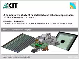
Lorentz angle measurements on irradiated strip sensors. Andreas Nürnberg T. Barvich, W. de Boer, A. Dierlamm, F. Hartmann, Th. Müller, M. Schmenger, T. Schneider (ITEP), P. Steck 19th RD50 Workshop, CERN, 22 November 2011. Outline. Lorentz angle measurement in summer 2011 Sensors used

E N D
Lorentz angle measurements on irradiated strip sensors Andreas Nürnberg T. Barvich, W. de Boer, A. Dierlamm, F. Hartmann, Th. Müller, M. Schmenger, T. Schneider (ITEP), P. Steck19th RD50 Workshop, CERN, 22 November 2011
Outline • Lorentz angle measurement in summer 2011 • Sensors used • Jumbo magnet at ITEP • Lorentz shift in irradiated sensors • Lorentz shift vs. bias voltage • Comparison to LA in CMS pixel sensor • Summary & Outlook Andreas Nürnberg Institut für Experimentelle Kernphysik, KIT
Measurements in Summer 2011 • 2 ½ weeks of measurements at 8T-Magnet during summer • 6 PCBs carrying 6 HPK sensors • 2 PCBs carrying 3 Micron sensors (FZ & MCz N-on-P) • Several fluences • 2 annealing steps • In total: ~16.000 single measurements of Lorentz angle 6 HPK sensors per PCB 3 Micron sensors per PCB Andreas Nürnberg Institut für Experimentelle Kernphysik, KIT
Sensors used • HPK Sensors • 6 different materials (320µm, 200µm, Floatzone P-on-N & N-on-P ( p-stop (p) & p-spray (y) ) • 80µm pitch • 6 Sensors per PCB • Mixed irradiation to 5 fluences (up to 5.8*1015 neq/cm2) + 1 non-irradiated sensor as reference • Annealing 4d@RT and ~27d@RT for Floatzone 320µm N & p-stop • Micron Sensors • 2 different materials (FZ & MCz, N-on-P) • 80µm pitch • 3 Sensors per PCB • Proton irradiation to 2.5*1014 neq/cm2 and 1*1015 neq/cm2 + 1 non-irradiated sensor as reference • Annealing 2d@RT and ~25d@RT Andreas Nürnberg Institut für Experimentelle Kernphysik, KIT
Jumbo magnet at ITEP, KIT • Superconducting magnet at Institute for Technical Physics, KIT • Up to 8T at room temperature • Probe is thermally insulated from liquid helium • 73mm diameter bore Andreas Nürnberg Institut für Experimentelle Kernphysik, KIT
Setup 6 sensors glued to PCB andbonded to APV-readout PCB mounted to aluminumsupport frame Openings in backsidemetallization of HPK sensors Optical Fibers Andreas Nürnberg Institut für Experimentelle Kernphysik, KIT
Lorentz shift vs. magnetic field (non-irradiated) n-strips • Linear increase of Lorentz shift Δx with magnetic field B expected • Hall mobility µH depends on temperature, bias voltage, irradiation, annealing,… • Shift of electrons and holes in opposite direction • Shift of electrons factor 3-4 larger than shift of holes • Shift larger in thick devices p-bulk Infrared Red 320µm N (h+) 200µm N (h+) 200µm P (e-) 320µm P (e-) Andreas Nürnberg Institut für Experimentelle Kernphysik, KIT
Cluster shape & laser wavelength Φ = 5.78*1015 neq/cm2 ↓ • Cluster shape depends on laserwavelength andirradiation • Gaussian is not the idealshape to fit to 1055nm signal • FZ320P (-40°C) • Lorentz shift of e-(p-bulk) decreaseswith irradiationto almost zero(as expected fromearlier measurements) Φ = 0 neq/cm2↓ 8T 0T λ = 1055nm → 8T 0T λ = 880nm → Andreas Nürnberg Institut für Experimentelle Kernphysik, KIT
FZ320P (electronreadout) Shift increases linearly with magnetic field Irradiation reduces slope decrease of shift with fluence Lorentz shift of electrons (P and Y) decreases with fluence Shift increases for holes (N) Lorentz shift (irradiated) 1000V 1000V 600V Fluence (h+) (e-, p-stop) (e-, p-spray) Andreas Nürnberg Institut für Experimentelle Kernphysik, KIT
Bias voltage (non-irradiated) • Lorentz shift shows strong dependence on bias voltage, especially in non-irradiated sensors • Largest shift at depletion voltage • Bias voltage larger than depletion voltage: Shift independent of actual depletion voltage (p-type, 1055nm) ≤25V 75V 20V 80V 250V 260V Andreas Nürnberg Institut für Experimentelle Kernphysik, KIT
Bias Voltage • Small depleted volume: small Lorentz shift Andreas Nürnberg Institut für Experimentelle Kernphysik, KIT
Bias Voltage • Small depleted volume: small Lorentz shift • Increase in bias voltage: increasing shift Andreas Nürnberg Institut für Experimentelle Kernphysik, KIT
Bias Voltage • Small depleted volume: small Lorentz shift • Increase in bias voltage: increasing shift • Bias at depletion voltage: shift reaches maximum Andreas Nürnberg Institut für Experimentelle Kernphysik, KIT
Bias Voltage • Small depleted volume: small Lorentz shift • Increase in bias voltage: increasing shift • Bias at depletion voltage: shift reaches maximum • Bias larger than depletion voltage: Increasing electric field leads to higher drift velocity smaller shift Andreas Nürnberg Institut für Experimentelle Kernphysik, KIT
Bias Voltage (irradiated) • Irradiated p-type sensors (V_depl < 1000V) added to plot • Above depletion voltage, Lorentz shift still independent of depletion voltage and irradiation fluence (p-type, 1055nm) • Valid for mixed irradiated HPK sensors and proton irradiated Micron sensors of same thickness HPK FZ MicronFZ MicronMCz Andreas Nürnberg Institut für Experimentelle Kernphysik, KIT
Comparison to LA in CMS pixel sensor • CMS n-on-n pixel sensor • Direct measurement of the charge drift in the magnetic field using the grazing angle method in pion testbeam • Projection of particle track tosensor surface gets deflected • Micron FZ n-on-p strip sensor:good agreement with data frompixel testbeam From: A. Dorokhov et al.,Tests of silicon sensors for the CMS pixel detector, Nucl. Instr. and Meth. A 530 (2004), 71-76 Andreas Nürnberg Institut für Experimentelle Kernphysik, KIT
Summary & Outlook • Lorentz angle has been measured on HPK floatzone and Micron floatzone and magnetic-czochralski mini strip sensors • Lorentz shift vs. magnetic field shows linear behavior • Shift of electrons decreases with fluence • Shift of holes increases with fluence • Lorentz shift depends strongly on bias voltage • Lorentz shift obtained with 1055nm laser in p-type sensor is independent of depletion voltage, if bias voltage is larger than depletion voltage • Comparison to Lorentz angle measurement in CMS pixel sensor shows good agreement • Next measurement time at magnet is planned for the first half of 2012 • Investigate magnetic-czochralski sensors produced by HPK • Perform further annealing step Andreas Nürnberg Institut für Experimentelle Kernphysik, KIT
Backup Andreas Nürnberg Institut für Experimentelle Kernphysik, KIT
Shift: 6 µm Shift: 11 µm FZ320N 6.6*1014 FZ320P 3.8*1015 Andreas Nürnberg Institut für Experimentelle Kernphysik, KIT
Annealing Andreas Nürnberg Institut für Experimentelle Kernphysik, KIT
HPK FZ320P Normalized to 0T Normalized to0 neq/cm^2 20% 50% KA Hardware Meeting - Andreas Nürnberg
HPK FZ320Y • Normalized to 0T • Normalized to0 neq/cm^2 10% 50% KA Hardware Meeting - Andreas Nürnberg
HPK FZ320N • Normalized to 0T • Normalized to0 neq/cm^2 <10% 10% KA Hardware Meeting - Andreas Nürnberg
Micron NinP FZ & MCz • Normalized to 0T • Normalized to0 neq/cm^2 0% <10% +5% <10% KA Hardware Meeting - Andreas Nürnberg
Abstract • Lorentz angle measurements on irradiated strip sensors • Lorentz angle measurements on mixed-irradiated mini strip-sensors have been performed as part of the CMS HPK Campaign. Up to now, the study covers 320µm and 200µm thick n- and p-bulk floatzone sensors at a magnetic field of up to 8T at different temperatures and after two annealing steps. In addition to that, proton irradiated magnetic-czochralski and floatzone n-on-p sensors produced by Micron were examined. This talk gives an overview of the obtained results. Andreas Nürnberg Institut für Experimentelle Kernphysik, KIT