Download
1 / 20
200 likes | 408 Views
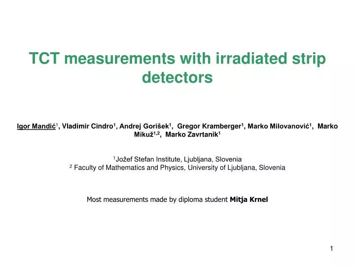
TCT measurements with irradiated strip detectors Igor Mandić 1 , Vladimir Cindro 1 , Andrej Gorišek 1 , Gregor Kramberger 1 , Marko Milovanović 1 , Marko Mikuž 1,2 , Marko Zavrtanik 1 1 Jožef Stefan Institute, Ljubljana, Slovenia

E N D
TCT measurements with irradiated strip detectors Igor Mandić1, Vladimir Cindro1, Andrej Gorišek1,Gregor Kramberger1,Marko Milovanović1, Marko Mikuž1,2, Marko Zavrtanik1 1Jožef Stefan Institute, Ljubljana, Slovenia 2 Faculty of Mathematics and Physics,University of Ljubljana, Slovenia Most measurements made by diploma student MitjaKrnel
Introduction: • TCT with focused IR laser light • light beam directed on the surface of strip detector: Top-TCT • “Spaghetti” detectors produced by Micron: • - p-type, FZ, 300 µm thick, 4x4 mm2 • - strip pitch: 80 µm • - implant width: 20 µm, DC coupled • Spaghetti: all strips connected on one side • only one wire bond faster work… • E field as in strip detector, weighting field as in pad detector • Spaghetti Type 1 500 µm of implant not covered by metal • detectors irradiated to 1∙1015 , 2∙1015 and 5∙1015 n/cm2 • measurements after several annealing steps at 60°C up to total annealing of • 5120 minutes at 60°C • Motivation: check the uniformity of response • withSpaghetti T1 laser measurement possible also under implants
Setup detector HV Peltier controller beam diameter in the silicon FWHM~7 mm y table optical fiber & focusing system Cooled support Detector box width of light pulses ~ 100 ps , repetition rate 200 Hz cooling pipes z table x table Bias-T 1GHz oscilloscope fast current amplifier Laser Laser driver trigger line
Detector Last 500 µm of implants not covered with metal 4 mm • All strips connected together • E field as in strip detector • weighting field as pad • detector • signal is a sum of • currents induced on all • strips
Signals Guardring • before irradiation • bias = 100 V (depleted) No metal metal scan laser spot across the surface Signals induced by laser beam at different locations: Before irradiation Bias = 100 V
Before irradiation: scanoverdetectorsurface (step x: 2.5 µm, y: 50 µm) Bias = 100 V (depleted) End of implants Charge = integral of current pulse (offline) Guardring Metal
Before irradiation Bias = 100 V Reflection from metal guard ring no metal Some signal also when beam on metal tails of light spot No significant difference between metal and no-metal! metal
Irradiated detector Φeq= 5·1015 n/cm2 Bias = 1000 V Annealed 5120 minutes at 60°C multiplication expected Large signals close to guard ring End of implants
Irradiated detector Φeq= 5·1015 n/cm2; Bias = 1000 V; Annealed 5120 minutes at 60 C high signals also near the guard-ring parallel to the strip strips Guard ring
Irradiated detector Φeq= 5·1015 n/cm2 Bias = 1000 V Annealed 5120 minutes at 60°C Δt = 0.2 ns Δt = 0.6 ns Δt = 0.7 ns Step: 50 µm (dot colors correspond to line colors) guard ring v = 107cm/s Δt ~ 0.5 ns v·Δt ~ 50 µm no metal metal The second peak from high field at the end of implant.
Irradiated detector Φeq= 5·1015 n/cm2 ,Bias = 1000 V, annealed 5120 minutes at 60°C guard ring Pulses from scan over “no metal” part nometal metal Pulses from scan over “metal” Scan over “no metal” Scan over “metal” Complicated behavior near guardrings!
Irradiated detector Φeq= 5·1015 n/cm2 , Bias = 1000 V Signals on edges increase with long term annealing multiplication effects 80 min at 60°C 320 min at 60°C 1280 min at 60°C 5120 min at 60°C
Irradiated detector: effect of annealing Φeq= 5·1015 n/cm2; Bias = 1000 V; implant Scan over non metalized implants (~ 0.5 mm from guard ring) 1000 V Scan over metalizedstrips ~ 1 mm from guard ring 1000 V • more non-uniform with annealing multiplication at the edge of implants • effect increases closer to guard-ring
Annealing Φeq= 5·1015 n/cm2 Bias = 1000 V implant • Annealing of CCE depends on • location • Increase of charge with long term • annealing near implant edge
Irradiated detector: annealing at lowerbiasvoltage 600 V Bias = 600 V; Φeq= 5·1015 n/cm2; implant Scan over non metalized implants ~ 0.5 mm from guard ring 600 V Scan over metalizedstrips ~ 1 mm from guard ring • smaller changes of charge variations with annealing • charge drops with reverse annealing no (or less) multiplication
Voltage scan 2e15, annealed 5120 min 5e15, annealed 5120 min Charge variations increase with bias voltage!
Spaghetti detectors: • all strips connected sum of signals from all strips measured • opposite polarity contributions from neighbor strips added • variations of CCE dumped in spaghetti detectors! Hamamatsu detector irradiated to 1015 , ~5000 min at 60C, only one strip connected to amplifier: (see talk from Bari: https://indico.cern.ch/materialDisplay.py?contribId=5&sessionId=5&materialId=slides&confId=175330) Red: measured Blue: sum of signals from all strips at equivalent location: metalized strips to amplifier
Summary • Top – TCT measurements with spaghetti detectors • large signals (multiplication) close to guard ring • care should be taken to get realistic CCE (e.g. in test beam ….) • largest charge measured at edges of implants • signs of charge multiplication (annealing behavior, bias dependence … ) • largest at the edge of implant • variations of collected charge across detector increase with multiplication • variations are dumped in spaghetti diodes because of negative contributions • from neighbor strips • test beam experiment can tell how problematic are these variations, if there • are dead regions where CCE falls below threshold …. • ( in HEP experiments most tracks are crossing the detector at an angle)
AnnealingΦeq= 2·1015 n/cm2 Bias = 1000 V • larger non-uniformity after long • annealing • annealing of CCE depends on • location • increase of charge with long • annealing larger closer to • implant edge
AnnealingΦeq= 2·1015 n/cm2 Bias = 1000 V metal • slightly different behavior at larger • distance from guard-ring