Download
1 / 25
250 likes | 532 Views
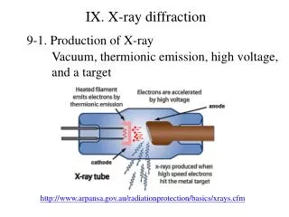
Workshop on cryogenic & vacuum sectorisation of the SPL Vacuum Sectorisation. Paul Cruikshank, CERN Technology Department (TE) Vacuum Surfaces & Coatings Group (VSC). Topics. Typical Vacuum Instrumentation Cold & RT beam vacuum Cryostat insulation vacuum LHC & LEP inputs

E N D
Workshop on cryogenic & vacuum sectorisation of the SPLVacuum Sectorisation Paul Cruikshank, CERN Technology Department (TE) Vacuum Surfaces & Coatings Group (VSC)
Topics • Typical Vacuum Instrumentation • Cold & RT beam vacuum • Cryostat insulation vacuum • LHC & LEP inputs • LHC Vacuum sectorisation • LEP cavity experience • Sectorisation Variants for SPL • Advantages / Disadvantages Vacuum Sectorisation
Vacuum Sectorisation Typical Beam VacConfig
Vacuum Sectorisation Typical Insulation Vac Config
LHC; Arcs and LSS Arcs: - 8 x 2.8 km = 22.4 km - cryomagnets in a continuous cryostat LSS (Long Straight Sections): - up- and downstream of the experiments - 8 x 2 x 250 m = 4 km - room temp and standalone cryo-magnets Cryogenic distribution line QRL LHC arc LHC LSS
LHC Vacuum Overview > 300 beam subsectors 6
LHC Vacuum Overview A few numbers….
Vacuum sectorisation LHC Vacuum Sectorisation • LHC Sectorisation Working Group setup in 1995 • Consider beam vacuum, insulation vacuum, cryogenic layout • Increased flexibility ? • Reduce down-time ? • Analyse types of intervention • Short – diode replacement, weld repair,instrument repair • Long – change of cryomagnet • Additional equipment required? • Implementation Cost ? • LHC Project Report #60 – September 1996 • Quantifications, recommendations, (dis)advantages, costs
Vacuum sectorisation LHC Sectorisation • Long Straight sections • Low density of cold magnets (30+20+10+10m cryostats in 250m) & lots of RT equipment – needed helium distribution line • Beam vacuum sectorisation at each cold warm transition (CWT) • Arc • Coherent vacuum & cryogenic subsectors to allow local warm-up of 2.8 km continuous cryostat • Vacuum barriers and helium plugs every 214 metres - compromise between staged installation, leak localisation, partial warm-up, additional heat inleaks, limit degraded vacuum • No beam vacuum sectorisation in 2.8 km continuous cryostat • QRL • Separation of QRL vacuum from magnet vacuum to allow staged reception and leak localisation in long cryostats
Insulation Vacuum (3) QRL cryostat Vacuum barriers Jumpers LHC magnet cryostat 11
Baseline ‘short interventions’in insulation vacuum subsectors • Scenario from LHC Project Report 60 • Vacuum barriers every 214m • n-2…. floating, cold, under vacuum • n-1 thermal buffer, RT, under vacuum • n intervention, RT, vented, W opened • n+1 thermal buffer, RT, under vacuum • n+2…. floating, cold, under vacuum • With subsector length of 214m, it is necessary to warm-up 642m of the 2.8 km continuous cryostat • Egrepairs on diode, busbar, line Y, helium leak….but no intervention on beam vac n-2 n-1 n n+1 n+2
Sectorisation of LEP RF CavitiesBeam Vacuum • Commissioning and installation • During the installation and commissioning, the RF cavities shall stay under vacuum to: • Limit the contamination by dusts • Without any sectorisation, several venting will be required, increasing the risk of dust contamination. • Preserve the RF commissioning on surface • Venting always implies repeating partly the RF commissioning • During the pre-commissioning on the surface, absorber blocks have to be installed on the other side of the sector valves to absorb the accelerated electrons emitted by field emission. Once installed in the LEP tunnel, the sector valves were the absorbers. • Modules were warmed individually to change tuners or couplers.
Sectorisation of LEP RF CavitiesBeam Vacuum • RF processing is required to increase the accelerating field above 6 MV/m • Injection of helium (5.10-6 mbar, reading on the gauge) onto the cold (4.5 K) RF cavity. • Sequence is as follow: • Installation of a pumping group with an helium injection line (4 h) • Bake out (24 h) • Helium injection (3 h) …RF processing… • Helium pump down (10 h minimum) needs a partial warm-up to release the condensed helium • Need that each module is sectorised to allow for an RF processing
Vacuum sectorisation SPL Sectorisation Variants Continuous Segmented Option A Segmented Option B
Vacuum sectorisation Typical Insulation Vac Config • Cost for vacuum system: • Draft estimate from S. Calatroni • Includes instrumentation, controls, cabling, in-situ leak test • Insulation vacuum subsector ~ 90 kCHF • Beam vacuum ‘cell’ ~ 90kCHF (cold) + 90kCHF (RT with valves)
SPL Sectorisation Variants Vacuum sectorisation 17 09-11-09
Vacuum Sectorisation Design aspects – vacuum Segmented Continuous • Advantages • More modular design • Minimise cold equipment – access, alignment, repairs, upgrades, unecessary outgassing, leaks, etc • Modules are complete & tested before installation • Disadvantages • More vacuum equipment eg cold to warm transitions, intermodules • More vacuum instrumentation • Advantages • Compact longitudinal layout – fewer CWT, fewer RF contacts • Helium transfer line can be integrated – less vac systems • Disadvantages • Beam vacuum sectors long- cold sector valves don’t exist! • Some sensitive equipment is imprisoned in cryostat - needs vacuum compatibility and validation
Vacuum sectorisation Installation aspects – vacuum Segmented Continuous • Advantages • Minimise tunnel work and problems - modules are complete and tested before installation • Fewer problems treated on-line • Staged acceptance tests • Decoupling of problems • Disadvantages • Beam and insulation vacuum systems are exposed to tunnel environment – dust contamination?
Vacuum Sectorisation Repair aspects – vacuum Segmented Continuous • Advantages • Reduced search zone • Decoupling of repair and other activities • Limit zones of warm-up and opening of vacuum system – cost & downtime • Disadvantages • Difficult access at cold to warm transitions – not std interconnect design • Advantages • Less tasks for systematic repairs on modules – venting, repumping.. • Disadvantages • Equipment will see more thermal cycles – create leaks?
Vacuum Sectorisation Commissioning aspects – vacuum Segmented Continuous • Advantages • Precommissioning before installation • Staged tests – smoothing of resources, earlier identification of problems • Decoupling of problems • Recommissioning of ‘weak’ module possible • Disadvantages • More volumes to commission • Disadvantages • Cavities need to be recommissioned if vented • RF processing with helium required for field above < 6 MV/m – complicated • Movable blocks or valves to absorb field emission electrons?
Vacuum Sectorisation Operational aspects – vacuum Segmented Continuous • Advantages • Limit zone of degraded ins vacuum (helium leak) • Easier diagnosis of problems • Disadvantages • More equipment (fixed pumping systems & valves) • More interlocks • More risk of equipment failure • More maintenance • Advantages • Simpler controls • Redundancy in fixed pumping systems • Disadvantages • MCI would affect more equipment
Vacuum Sectorisation SPL VacSectorisation – next steps • Which sectorisation variants are not possible? • Strong vacuum constraints need to be identified & investigated – eg can we expose cavity to tunnel air, etc. • Constraints for other technologies to be confirmed • For retained variants, advantages and disadvantages presently expressed qualitatively, now need to be quantified in time, manpower and expenditure. • Are there other vacuum aspects to add? • Continue to get feedback from other operational machines
Last Slide Thanks for your attention Vacuum Sectorisation
Semi-standalone cryo-magnet- typical installation and leak test sequence - CRYOGENIC DISTRIBUTION LINE (QRL) JUMPER HELIUM CIRCUIT BEAM VACUUM TUBES CRYO-MAGNET CRYO-MAGNET DETECTOR DETECTOR PUMP + DETECTOR PUMP+ DETECTOR ITER/CERN Collaboration - LHC Insulation Vacuum - Paul Cruikshank - 25 June 2009