Download
1 / 12
120 likes | 210 Views
Chapter 4 Network Layer. Computer Networking: A Top Down Approach 6 th edition Jim Kurose, Keith Ross Addison-Wesley March 2012. CPSC 335 Data Communication Systems Readings: 4.1, 4.4.1, David Nguyen Adapted from Kurose Ross. Chapter 4: network layer. chapter goals:

E N D
Chapter 4Network Layer Computer Networking: A Top Down Approach 6th edition Jim Kurose, Keith RossAddison-WesleyMarch 2012 • CPSC 335 Data Communication Systems • Readings: 4.1, 4.4.1, • David Nguyen • Adapted from Kurose Ross Transport Layer
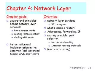
Chapter 4: network layer chapter goals: • understand principles behind network layer services: • network layer service models • forwarding versus routing • routing (path selection) • broadcast, multicast • instantiation, implementation in the Internet Network Layer
4.1 introduction 4.2 virtual circuit and datagram networks 4.3 what’s inside a router 4.4 IP: Internet Protocol datagram format IPv4 addressing ICMP IPv6 4.5 routing algorithms link state distance vector hierarchical routing 4.6 routing in the Internet RIP OSPF BGP 4.7 broadcast and multicast routing Chapter 4: outline Network Layer
transport segment from sending to receiving host on sending side encapsulates segments into datagrams on receiving side, delivers segments to transport layer network layer protocols in everyhost, router router examines header fields in all IP datagrams passing through it network data link physical network data link physical network data link physical network data link physical network data link physical network data link physical network data link physical network data link physical network data link physical network data link physical network data link physical application transport network data link physical application transport network data link physical Network layer Network Layer
Two key network-layer functions analogy: • routing: process of planning trip from source to dest • forwarding: process of getting through single interchange • forwarding: move packets from router’s input to appropriate router output • routing: determine route taken by packets from source to dest. • routing algorithms Network Layer
routing algorithm local forwarding table header value output link routing algorithm determines end-end-path through network forwarding table determines local forwarding at this router 0100 0101 0111 1001 3 2 2 1 value in arriving packet’s header 1 0111 2 3 Interplay between routing and forwarding Network Layer
Connection setup • 3rd important function in some network architectures: • before datagrams flow, two end hosts and intervening routers establish virtual connection • routers get involved • network vs transport layer connection service: • network: between two hosts (may also involve intervening routers in case of VCs) • transport: between two processes Network Layer
4.1 introduction 4.2 virtual circuit and datagram networks 4.3 what’s inside a router 4.4 IP: Internet Protocol datagram format IPv4 addressing ICMP IPv6 4.5 routing algorithms link state distance vector hierarchical routing 4.6 routing in the Internet RIP OSPF BGP 4.7 broadcast and multicast routing Chapter 4: outline Network Layer
host, router network layer functions: • IP protocol • addressing conventions • datagram format • packet handling conventions forwarding table The Internet network layer transport layer: TCP, UDP • routing protocols • path selection • RIP, OSPF, BGP network layer • ICMP protocol • error reporting • router “signaling” link layer physical layer Network Layer
IP protocol version number 32 bits total datagram length (bytes) header length (bytes) type of service head. len ver length for fragmentation/ reassembly fragment offset “type” of data flgs 16-bit identifier max number remaining hops (decremented at each router) upper layer time to live header checksum 32 bit source IP address 32 bit destination IP address upper layer protocol to deliver payload to e.g. timestamp, record route taken, specify list of routers to visit. options (if any) data (variable length, typically a TCP or UDP segment) IP datagram format how much overhead? • 20 bytes of TCP • 20 bytes of IP • = 40 bytes + app layer overhead Network Layer
network links have MTU (max.transfer size) - largest possible link-level frame different link types, different MTUs large IP datagram divided (“fragmented”) within net one datagram becomes several datagrams “reassembled” only at final destination IP header bits used to identify, order related fragments … … reassembly IP fragmentation, reassembly fragmentation: in: one large datagram out: 3 smaller datagrams Network Layer
length =1500 length =1500 length =4000 length =1040 ID =x ID =x ID =x ID =x fragflag =0 fragflag =1 fragflag =1 fragflag =0 offset =0 offset =0 offset =370 offset =185 one large datagram becomes several smaller datagrams IP fragmentation, reassembly example: • 4000 byte datagram • MTU = 1500 bytes 1480 bytes in data field offset = 1480/8 Network Layer