Download
1 / 66
700 likes | 989 Views
Radio Signal Propagation. Learning Objectives. Upon successful completion of this lesson, you will be able to:. Describe how gain is accomplished in Non-isotropic radiators. Using the dB scale, calculate an increase/decrease in gain, and explain the affects of the results.

E N D
Learning Objectives Upon successful completion of this lesson, you will be able to: • Describe how gain is accomplished in Non-isotropic radiators. • Using the dB scale, calculate an increase/decrease in gain, and explain the affects of the results. • Define how the beam-width of an antenna is measured. • Define the FCC –1/+3 rule for 2.4 GHz Point-to-Point applications. • Define Effective Isotropic Radiated Power (EIRP), and it’s impact on Link Budget.
Learning Objectives, cont. Upon successful completion of this lesson, you will be able to: • State the difference between Clear Line-of-Site and Radio Line-of-Site. • Define Fresnel Zone, and its impact on Link Budget. • Define Multi-path propagation, and it’s impact on throughput. • Explain the purpose of incorporating Fade Margin in the Link Budget. • Calculate a link budget for a given scenario.
dB (decibel) • The difference (or ratio) between two signal levels; used to describe the effect of system devices on signal strength. • For example, a cable has 6 dB signal loss or an amplifier has 15 dB of gain. • This is useful since signal strengths vary logarithmically, not linearly. Since the dB scale is a logarithmic measure, it produces simple numbers for large-scale variations in signals.
dB (decibel) • Every time you double (or halve) the power level, you add (or subtract) 3 dB to the power level. This corresponds to a 50 percent gain or reduction. • A 10 dB gain/loss corresponds to a tenfold increase/decrease in signal level. • A 20 dB gain/loss corresponds to a hundred-fold increase/decrease in signal level. • In other words, a device (like a cable) that has 20 dB loss through it will lose lots of its signal by the time it gets to the other side.
dBm (dB milliWatt) • A signal strength or power level; 0 dBm is defined as 1 mW (milliWatt) of power into a terminating load such as an antenna or power meter. Small signals are negative numbers (e.g. -83 dBm). • For example, typical 802.11b WLAN cards have +15 dBm (32mW) of output power. They also spec a -83 dBm RX sensitivity (minimum RX signal level required for 11Mbps reception). Additionally, 125 mW is 21 dBm, and 250 mW is 24 dBm.
dBd (dB dipole) • The gain an antenna has over a dipole antenna at the same frequency. The term dBd (sometimes just called dB) generally is used to describe antenna gain for antennas that operate under 1GHz (1000Mhz).
dBi (dB isotropic) • The gain a given antenna has over a theoretical isotropic (point source) antenna. Unfortunately, an isotropic antenna cannot be made in the real world, but it is useful for calculating theoretical fade margins. The gain of microwave antennas (above 1 GHz) is generally given in dBi. A dipole antenna has 2.15 dB gain over a 0 dBi isotropic antenna. So if an antenna gain is given in dBd, not dBi, add 2.15 to it to get the dBi rating. • For example, if an omni antenna has 5 dBd gain, it would have 5 + 2.15 = 7.15 dBi gain.
EIRP (Effective Isotopic Radiated Power) • The effective power found in the main lobe of a transmitter antenna relative to an Isotropic radiator which has 0 dB of gain. It is equal to the sum of the antenna gain (in dBi) plus the power (in dBm) into that antenna. • For example, if a 12 dBi gain antenna is fed with 15 dBm of power has an Effective Radiated Power (ERP) of: • 12 dBi + 15dBm = 27 dBm (500 mW). • 12 dBi + 24dBm = 36 dBm (4 Watts), which is the same as 1W (+30 dBm) into a 6 dBi omni. • 6 dBi + 30 dBm = 36 dBm (4 Watts).
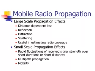
Unlicensed Band Characteristics • 900 MHz • Great propagation through foliage etc. • Small number of frequencies • High power equipment on either side of spectrum • 2.4 GHz ISM • Relatively Good Propagation • Relatively Good Wall Penetration • Required Interference Resistance (Processing Gain) • Heavy Interference May Be Found • 5.8 GHz ISM • Relatively Poor Propagation • Relatively Poor Wall Penetration • Requires Advanced Modulation to overcome extreme losses (i.e. OFDM)
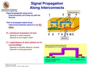
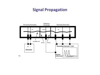
Modulation (Modem) Up Conversion & Amplification Down Conversion & Amplification Demodulation (Modem) Antenna Couples Energy To / From Channel Antennas
Antennas • Antennas Couple Energy Into Space • Theoretical Isotropic Antenna Couples Energy Equally In All Directions (Sphere) • Real World Antennas Do Not Radiate In Perfect Spheres
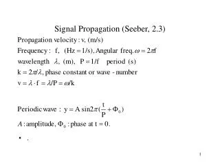
RF Generator Antenna Basics Definition f = ג / c or ג = c / f ג (wavelength) = c ( 300,000 km/sec) / f (Hz) f = 900 MHz ג = 33.33 cm 13.123” f = 2.4 GHz ג = 12.5 cm 4.92” f = 5.8 GHz ג = 5.17 cm 2.03”
Antenna Characteristics • Antenna Gain • Accomplished by compressing the radiation pattern of the antenna into a narrower beam width and focusing the energy in one direction. • Defined as the ratio between radiation intensity of the main lobe and the radiation intensity of an isotropic radiator (having the same input power). • Antenna Gain is expressed in dBi.
R C V G e n e r a t o r 17 dBm = 50 mW Antennas • The power fed into the antenna is radiated in the whole space. • Receiver exposed to a portion of the power which has been spread across whole sphere. Isotropic Antenna (Theoretical)
Generator 17 dBm/50 mW RCV Antenna Gain Example • An antenna with 3 dBi gain, radiates its energy into 50% of the space. • Conclusion: A 3 dBi antenna fed with 17 dBm behaves (in its active field) as an isotropic antenna fed with 20dBm Isotropic Antenna
Non-Isotropic Antenna (Real) R C V G e n e r a t o r 17 dBm/50 mW Antennas • The energy is radiated only to part of the space. • Receiver is exposed to a portion of the power, which has been spread across a cone, which is much more concentrated than sphere volume (radiation) of subject antenna volume (radiation) of isotropic antenna Antenna gain =
RCV Generator 17 dBm (50 mW) Non-Isotropic Antenna (Real) • For same amount of energy fed into the antenna, a non-isotropic antenna will transmit its signal over longer distances. • Non-isotropic antennas are characterized by their capability to focus the transmitted energy, expressed by the antenna gain.
Antenna Characteristics • AntennaPolarization • The direction of vibration of the electromagnetic wave. • Antenna polarization should be the same at both ends of the link. • In most applications, the orientation is vertical polarization. • Above-ground propagation of the signal is better when it is polarized vertically.
Antenna Characteristics • Antenna Beam width • The Radiation Pattern of an antenna is defined as ‘the angle between two half-power (+/-3 dB) points on either side of the main lobe of radiation.
Antennas • Omni-Directional Antenna • Radiates and receives equally in all directions in azimuth (and has a directional pattern in elevation). • Uni-Directional Antenna • Radiates and receives most of the signal power in one directions.
RF Behaviour The antenna is located here • All antennas behave with isotropic properties: • Energy is radiated in every direction from the radiating elements of the antenna • An omni-directional antenna is designed to radiate in 360° horizontally • A uni-directional antenna is designed to radiate in a much smaller horizontal area These concentric circles represent the ever increasing area of the radiated energy.
RF Behaviour In this drawing, we see a 90° sectoral antenna depicted. The antenna radiates energy in every direction, but radiates much more energy within the designed beamwidth of the antenna. This drawing is depicted as a horizontal “slice” of the spherical radiation pattern of the antenna - RF radiates in 3D. This is antenna beamwidth Greatest Energy Least Energy
Example of Polar Chart - 3 dB
FCC Authorizations Part 15 • 15.247 Systems • 15.203 Proprietary Connectors • 15.204a Systems • 15.204b Amplifiers • 15.204c Antennas
FCC Rules Regarding Antennas 15.204c • Only authorized antennas • Fixed Antennas • Proprietary Connectors • Professional Installation • Installer Responsibility
FCC Guidelines • The Maximum Allowable Power Output of the Radio Card is 1 Watt (30 dBm). • Unlicensed Products must not cause interference for Licensed Frequencies. • Methods must be taken to discourage improper installations. • The FCC mandated that manufacturers prevent “uncertified” installations. • Maximum EIRP for Point to Multi-Point applications is 36 dBm. • Maximum EIRP for Point to Point applications is dependent upon the configuration (-1/+3 rule).
FCC Requirements (5.8 GHz) • No limits on antenna gain for point-to-point links. • Multi-point limits are 36 dBm for BU side of link. More on these later… • Paragraph from FCC 47CFR15.247: • (ii) Systems operating in the 5725 – 5850 MHz band that are used exclusively for fixed, point-to-point operations may employ transmitting antennas with directional gain greater than 6 dBi without any corresponding reduction in transmitter peak output power.
External Amplifiers • Unauthorized Use • Marketing of a Complete System • BreezeACCESS firmware does not support them
FCC Allowable EIRP Example Multipoint Systems (AU) Power Ant. Gain EIRP 30 + 6 = 36 4W Maximum 26 + 8 = 34 OMNI 8 & BAII IF 26 + 17.5 -.5 = 43 TOO MUCH!!! 19 + 17.5 -.5 = 36 OK! 26 + 13.5 -.5 = 39 STILL TOO MUCH!!! 23 + 13.5 -.5 = 36 OK!
FCC Allowable EIRP Example Point-to-Point Systems (AU & SU) Power Ant. Gain EIRP 30 + 6 = 36 4W 29 + 9 = 38 28 + 12 = 40 27 + 15 = 42 16W 26 + 18 = 44 25 + 21 = 46 24 + 24 = 48 64W
Free Space Loss (FSL) • As the signal propagates farther from the transmitting antenna, an antenna receiving the signal receives much less energy than the transmitter emits • The energy is dispersed in all directions from the transmitting antenna • The receiving antenna only “captures” a portion of the energy that is relational to the area of the antenna compared to the area that the transmitted energy is radiated over all
Free Space Loss • Free Space Loss is defined as the loss that a radio signal experiences when traveling through free space. The formula at 2.4 GHz is: 36.5 + 20 Log F[MHz] + 20 Log D[mile] At 2.4 GHz : 100 + 20 Log D[km] 104 + 20 Log D[mile] 104.2 dB for 1 mile118.2 dB for 5 miles 124.2 dB for 10 miles
Free Space Loss • Always measured between the center of the transmitting antenna to the center of the receiving antenna • Is independent of any antenna height or geographical obstructions between the antennas • FSL is the least amount of attenuation that can be expected between any two antennas. • Any obstructions between the antennas will always result in added attenuation.
Free Space Loss When path length is 5000 ft, the transmitted energy is dispersed over an area equal to the surface area of a sphere 5000 ft radius Transmitting antenna may have surface area of 1 sq. ft. The energy received is relational to the area of the transmitting antenna, the area of the receiving antenna, divided by the area the energy is dispersed over! High power transmitted results in very low power received even over a very short path length! Receiving antenna may have surface area of 1 sq. ft. or less
Line of Sight • Visual Line of Sight • Radio Line of Sight • Obscured Line of Sight • Fresnel Zone • Clearance
Radio Line of Sight and Signal Loss • RF frequencies require Radio Line of Sight (LOS) in order to minimize signal loss during transmission. • LOS assumes that at least 80% of the first Fresnel zone is unobstructed. • Fade or Link Margin • This is the available margin in dBm which can be sacrificed before the link is lost. • Obstructed LOS will decrease this margin. • Excessive free space loss over distance. • Multi-path.
Calculations • Fresnel Zone • Fresnel1 = • d1 = Distance to first obstruction of the Fresnel • d2 = Distance from the first obstruction of the Fresnel • Dt = total link distance in miles • f = frequency (in GHz) being used. • Fresnel2 = • The effects of higher order Fresnel zone reflections are minimal. • The 0.6 Fresnel zone needs to be clear in direct sequence spread spectrum systems (DSSS) and the 0.8 Fresnel zone clear for frequency hopping systems (FHSS).
60 – 80 % Fresnel Clearance 60% - 80% Fresnel Zone Antenna B Antenna A Obstructions Earth Curvature Approximate Antenna Height
System Characteristics • Receiver Sensitivity • The minimum signal level required for certain performance level.
What is Multipath? Incident Mode Transmitting antenna Receiving antenna This view is from above the antennas
What is Multipath? Obstruction in the path Transmitting antenna Receiving antenna The signal between the rays is attenuated by the obstruction This view is from above the antennas