Download
1 / 24
240 likes | 264 Views
Signal Propagation Basics. EECS 4215. Signal Propagation Ranges. Transmission range communication possible low error rate Detection range detection of the signal possible communication not possible Interference range signals may not be detected signals add to the background noise.

E N D
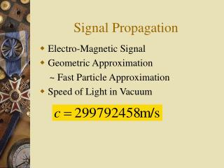
Signal Propagation Basics EECS 4215
Signal Propagation Ranges Transmission range communication possible low error rate Detection range detection of the signal possible communication not possible Interference range signals may not be detected signals add to the background noise sender transmission distance detection interference Note: These are not perfect spheres in real life!
Signal Propagation Propagation in free space is always like light (straight line). Receiving power proportional to 1/d² in vacuum – much more in real environments (d = distance between sender and receiver) Receiving power additionally influenced by fading (frequency dependent) Shadowing (blocking) reflection at large obstacles refraction depending on the density of a medium scattering at small obstacles diffraction at edges refraction shadowing reflection scattering diffraction
Propagation Modes • Ground-wave (< 2MHz) propagation • Sky-wave (2 – 30 MHz) propagation • Line-of-sight (> 30 MHz) propagation
Ground Wave Propagation • Follows the contour of the earth • Can propagate considerable distances • Frequencies up to 2 MHz • Example • AM radio • submarine communication (long waves)
Sky Wave Propagation • Signal reflected from ionized layer of atmosphere back down to earth • Signal can travel a number of hops, back and forth between ionosphere and the earth surface • Reflection effect caused by refraction • Examples • amateur radio • International broadcasts
Line-of-Sight Propagation • Transmitting and receiving antennas must be within line of sight • Satellite communication – signal above 30 MHz not reflected by ionosphere • Ground communication – antennas within effective line of sight due to refraction • Refraction – bending of microwaves by the atmosphere • Velocity of an electromagnetic wave is a function of the density of the medium • When wave changes medium, speed changes • Wave bends at the boundary between mediums • Mobile phone systems, satellite systems, cordless phones, etc.
Line-of-Sight Equations • Optical line of sight • Effective, or radio, line of sight • d = distance between antenna and horizon (km) • h = antenna height (m) (altitude relative to a receiver at the sea level) • K = adjustment factor to account for refraction caused by atmospherics layers; rule of thumb K = 4/3
Line-of-Sight Equations • Maximum distance between two antennas for LOS propagation: • h1 = height of antenna one • h2 = height of antenna two
LOS Wireless Transmission Impairments • Attenuation and attenuation distortion • Free space loss • Atmospheric absorption • Multipath (diffraction, reflection, refraction…) • Noise • Thermal noise
Attenuation • Strength of signal falls off with distance over transmission medium • Attenuation factors for unguided media: • Received signal must have sufficient strength so that circuitry in the receiver can interpret the signal • Signal must maintain a level sufficiently higher than noise to be received without error • Attenuation is greater at higher frequencies, causing distortion (attenuation distortion)
Free Space Path Loss • Free space path loss, ideal isotropic antenna • Pt = signal power at transmitting antenna • Pr = signal power at receiving antenna • = carrier wavelength • d = propagation distance between antennas • c = speed of light (» 3 ´ 10 8 m/s) where d and are in the same units (e.g., meters)
Free Space Path Loss in dB • Free space path loss equation can be recast (decibel version):
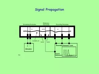
Multi-path Propagation Signal can take many different paths between sender and receiver due to reflection, scattering, diffraction Time dispersion: signal is dispersed over time interference with “neighbor” symbols, Inter Symbol Interference (ISI) The signal reaches a receiver directly and phase shifted distorted signal depending on the phases of the different parts multipath pulses LOS pulses signal at sender signal at receiver
Atmospheric Absorption • Water vapor and oxygen contribute most • Water vapor: peak attenuation near 22GHz, low below 15Ghz • Oxygen: absorption peak near 60GHz, lower below 30 GHz. • Rain and fog may scatter (thus attenuate) radio waves. • Low frequency band usage helps.
Effects of Mobility Channel characteristics change over time and location signal paths change different delay variations of different signal parts different phases of signal parts quick changes in the power received (short term fading) Additional changes in distance to sender obstacles further away slow changes in the averagepower received (long term fading) long term fading power t short term fading
Fading Channels • Fading: Time variation of received signal power • Mobility makes the problem of modeling fading difficult • Multipath propagation is a key reason • Most challenging technical problem for mobile communications
Types of Fading • Short term (fast) fading • Long term (slow) fading • Flat fading – across all frequencies • Selective fading – only in some frequencies • Rayleigh fading – no LOS path, many other paths • Rician fading – LOS path plus many other paths
Dealing with Fading Channels • Error correction • Adaptive equalization • attempts to increase signal power as needed • can be done with analog circuits or DSP (digital signal processor)
Reading • Mobile Communications (Jochen Schiller), section 2.4 • Stallings, chapter 3