Download
1 / 57
590 likes | 741 Views
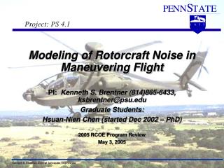
A PhD Thesis Defense Presented to The Faculty of the Division of Graduate Studies By Gang Wang Advisor: Dr. Tim C. Lieuwen April 4, 2002. STUDY OF A LOW-DISPERSION FINITE VOLUME SCHEME IN ROTORCRAFT NOISE PREDICTION. Background LDFV Scheme Objectives Results Contributions & Conclusions

E N D
A PhD Thesis Defense Presented to The Faculty of the Division of Graduate Studies By Gang Wang Advisor:Dr.Tim C. Lieuwen April 4, 2002 STUDY OF A LOW-DISPERSION FINITE VOLUME SCHEME IN ROTORCRAFT NOISE PREDICTION
Background LDFV Scheme Objectives Results Contributions & Conclusions Recommendations OUTLINE
Helicopter has a wide range of military and civil applications. However, the high noise level associated with it greatly restricts its further applications. BACKGROUND
Three categories of rotor noise: Rotational noise: steady or harmonically varying forces, volume displacements Broadband noise: random disturbances Impulsive noise High-Speed-Impulsive (HSI) noise Blade-Vortex-Interaction (BVI) noise Rotorcraft Noise
Rotorcraft Noise High-Speed-Impulsive noise
Rotorcraft Noise Blade-Vortex-Interaction noise
Great efforts have been spent on quantifying and minimizing rotorcraft noise. Two noise prediction techniques: Fully computational aerodynamics and acoustics; High resolution CFD calculation in the near field coupling with acoustic analogy or Kirchhoff method in the far field; Noise Prediction
Noise Prediction Far Field Observer Acoustic calculation Region Blade CFD calculation Region
Near-field CFD calculation is critical to the accuracy of far-field noise prediction. Much progress has been made on understanding and predicting rotorcraft noise characteristics with the aid of CFD methods. Special attention is needed to simulate acoustic wave propagation with CFD methods. Noise Prediction
Differences between aerodynamic and aeroacoustic problems: Relative Magnitude Length and Frequency Scale Dispersion and dissipation errors generated by conventional CFD methods can easily change the observed noise characteristics. Noise Prediction
Noise Prediction T=50 T=100 T=0 Magnitude drops as wave propagates… Dissipation Dispersion Errors - some waves travel slower than the rest.
These errors must be reduced to give correct traveling-wave profile. Dispersion error minimization methods: Dispersion-Relation-Preserving (DRP) Scheme, by Dr. Tam and Web; Compact Scheme, by Dr. Lele; Low Dispersion Finite Volume (LDFV) Scheme, by Dr. Nance and Sankar; Noise Prediction
The spatial derivative is approximated by the difference of the numerical fluxes evaluated at the adjacent half points. LDFV SCHEME
The general interpolation formulations for the left and right physical fluxes are: The approximation of spatial derivative becomes: LDFV SCHEME
Expand uj+l about xj using classical Taylor series expansion, like: Specific spatial order scheme can be obtained by comparing corresponding coefficients of each term at both sides of the approximation equation. LDFV SCHEME
A further restriction is imposed to match the Fourier transform of the approximation of spatial derivative with its exact transform. The Fourier transform of the spatial difference approximation is: LDFV SCHEME Non-dimensional Wave Number F. T.
The least square error: should be minimized with respect to coefficients and . LDFV SCHEME Optimization Equations
Study dispersion and dissipation characteristics of LDFV scheme Apply LDFV scheme to rotorcraft noise prediction OBJECTIVES
Analysis of dispersion and dissipation characteristics of LDFV scheme High-Speed-Impulsive or shock noise prediction Spherically symmetric wave propagation study RESULTS
The one-dimensional advection equation: Semi-discretization of advection equation: Discrete operator A is of the form: Analysis of LDFV Scheme
Full-discretization of advection equation written in operator notation: Z is time shift operator: Define an amplification factor: which satisfies characteristic equation Analysis of LDFV Scheme
The phase velocity of full-discretization: The amplitude error: Analysis of LDFV Scheme
Analysis of LDFV Scheme Phase Velocity, CFL=0.01
Analysis of LDFV Scheme Amplitude Error, CFL=0.01
The phase difference between predicted results and exact solution: The predicted amplitude: Analysis of LDFV Scheme
Analysis of LDFV Scheme Phase Difference Comparison at t=50 Fourier Transform Comparison at t=50
Analysis of LDFV Scheme Phase Difference Comparison at t=400 Fourier Transform Comparison at t=400
Both MUSCL and LDFV schemes can accurately capture low non-dimensional wave number components. LDFV scheme generates lower numerical errors for high non-dimensional wave number components than MUSCL scheme. The above observations are still kept as propagation distance increases although low error generation ranges are reduced. Comments on LDFV Scheme Analysis
1/7 scale model of untwisted rectangular UH-1H blades in hover condition NACA0012 airfoil Non-lifting case Shock Noise Prediction
Shock Noise Prediction C-H Computational Grid
Shock Noise Prediction Shock Noise Measurement Locations and Method
Grid Independence Study Acoustic Pressure Time History, MTip=0.90, r/R=3.09
MUSCL and LDFV scheme results are very similar. Two factors to be investigated: Flux Limiter Error generation Shock Noise Prediction
Flux limiter switches higher order schemes back to first order scheme in the large flux gradient regions. Different flux limiters will give different results in those regions. Flux Limiter Effects
What’s the non-dimensional wave number range of shock noise signal? Is the simulated domain large enough to see difference between the results of two schemes? Error Generation Issues
The spherically symmetric wave equation: Shock noise signal at sonic cylinder is chosen as initial condition. Spherically Symmetric Wave Propagation Study
Spherically Symmetric Wave Propagation Study kr=0.0614 Initial Acoustic Signal Distribution Spectrum of Initial Signal
Spherically Symmetric Wave Propagation Study Phase Difference at r=3.229m (Without Limiter) Fourier Transform of Signal Distributions at r=3.229m (Without Limiter)
Spherically Symmetric Wave Propagation Study Phase Difference at r=20.0m (Without Limiter) Fourier Transform of Signal Distributions at r=20.0m (Without Limiter)
Negative Pressure Peak Under-prediction Ratio (Without Limiter)
Spherically Symmetric Wave Propagation Study Phase Difference at r=3.229m (With Limiter) Fourier Transform of Signal Distributions at r=3.229m (With Limiter)