Download
1 / 18
180 likes | 325 Views
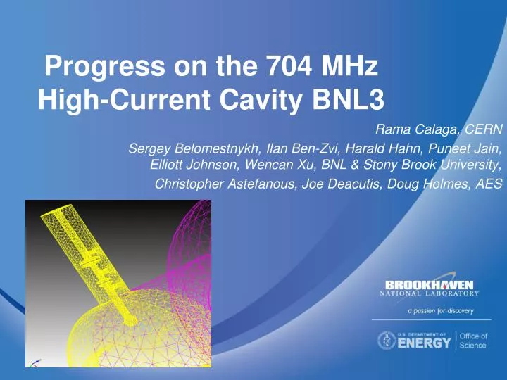
Progress on the 704 MHz High-Current Cavity BNL3. Rama Calaga , CERN Sergey Belomestnykh, Ilan Ben-Zvi, Harald Hahn, Puneet Jain, Elliott Johnson, Wencan Xu , BNL & Stony Brook University, Christopher Astefanous , Joe Deacutis , Doug Holmes, AES.

E N D
Progress on the 704 MHz High-Current Cavity BNL3 Rama Calaga, CERN Sergey Belomestnykh, Ilan Ben-Zvi, Harald Hahn, Puneet Jain, Elliott Johnson, WencanXu, BNL & Stony Brook University, Christopher Astefanous, Joe Deacutis, Doug Holmes, AES
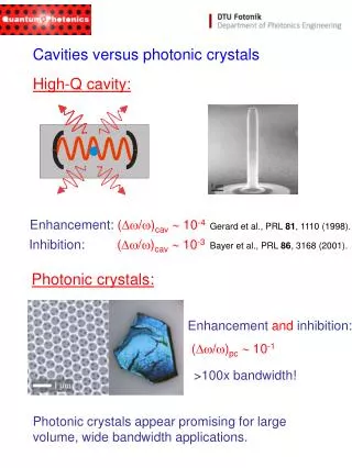
Five-cell SRF cavity with strong HOM damping HOM ports FPC port • A five-cell 703.8 MHz SRF cavity (BNL3) for high-current applications is under development. • We use our experience with BNL1 cavity. • The cavity is optimized and designed for applications such as eRHIC, ESS and SPL. • Reduced peak surface magnetic field -> reduced cryogenic load. • Three antenna-type couplers will be attached to a large diameter beam pipes at each end of the cavity and will provide strong HOM damping while maintaining good fill factor for the linac. • HOM tolerances from BBU simulations. SLHiPP/BNL3
eRHIC layout • The linac will consist of two halves (up to 60 cavities), connected in the middle to the cryogenic system operating at 1.9 K. • The linac design is in early conceptual phase. • At each end of the linac there will be a 1meter long endcap transition to room temperature. • To fit into available space in the IPs, we are designing very compact single-cavity cryounits with short, 8-cm, interconnects between them. • The cryounits will be “easily” replaceable. • There will be no magnets inside the linac. • The linac filling factor will be 0.64. SLHiPP/BNL3
Cryounit layout 2K 2-phase line HOM ports Modified Conflat gasket FPC LHe fill line 5-cell Nb cavity • The cavities in titanium helium vessels will be supported by nitronic rods. • There will be short (1-2 convolutions) bellows between the cryounits. • Modified Conflat seals with RF contact (similar to ones used in BNL ERL gun FPCs) will be used on beam pipes. RF contact SLHiPP/BNL3
Cavity operational characteristics • At 2K the tuner range is 350 kHz with a maximum load of 2200 lbs. . • The range depends on the maximum tuner load that can be generated. SLHiPP/BNL3
Magnetic fields near FPC end flange • Peak Magnetic Field limit is 175 A/m when flange is cooled to 5 K. SLHiPP/BNL3
Cavity vibrational modes at 2 K SLHiPP/BNL3
Cavity tunability SLHiPP/BNL3
HOM damping with antenna-type couplers HOM high-pass filter • A two-stage high-pass filter rejects fundamental frequency, but allows propagation of HOMs toward an RF load. • 1st HOM is at 0.82 GHz. SLHiPP/BNL3
HOM damping • Total HOM power to extract is 7.3 kW per cavity at eRHIC 3.5 nC, 50 mA, 6 passes up + 6 passes down energy (loss factor 3.5 V/pC). • Simulated a model with two HOM couplers per side using CST MWS. • High-Q modes at 1.62 GHz are sextupole ones and have low R/Q. • Qextrequired from BBU simulations for dipole modes is ~40,000. SLHiPP/BNL3
Next steps in HOM damping design • As significantly more computer resources are required, we use Omega3P. • Model with three HOM couplers at each end. • Adding FPC should fix mode polarization. • Finalize antenna length/position. • Add high-pass filter. • Simulate a string of cavities. • Compare results with measurements on the BNL3 copper model. SLHiPP/BNL3
The copper cavity prototype • Cavity was fabricated by AES. • Tuned to specs (98.5% field flattness). • Acceptance measurements are finished: ready to begin fabrication of Nb cavity. • Detail HOM studies will continue. Before Tuning After Tuning SLHiPP/BNL3
Measurement setup and model • Very weak coupling at both FPC and PU ports. • Whole copper, including the end plates at both sides. SLHiPP/BNL3
Q factors of Higher-Order-Modes • The simulated Q’s agree reasonably well with the measured Q’s for most of the modes. • As expected, the measured Q’s are a little lower than the simulated Q’s due to imperfect copper surface. • The modes with relatively low Q are the splitting modes. As the -3 dB bandwidth method is used, Q’s for some of such modes can not be measured correctly. We plan to improve this by using a more elaborate resonance curve fitting algorithm. SLHiPP/BNL3
HOM Spectrum Sextupole Quadrupole Dipole • All dipole modes are damped extremely well with the open beam pipes. • Two quadrupole modes around 1.21 GHz are distorted too much by the two different boundary conditions. • Two sextupole modes at 1.63 GHz are trapped, as expected from simulations. SLHiPP/BNL3
Niobium cavity configuration • Niobium cavity fabrication has started. • The plan is to finish cavity fabrication and perform vertical testing in 2012. • The design of the single-cavity cryomodule has begun with the goal to have the cryomodule complete by summer of 2013. • It will be used for Coherent electron Cooling Proof-of-Principle (CeCPoP) experiment in RHIC starting with Run-14. SLHiPP/BNL3
Summary • The BNL3 cavity has been designed in detail and optimized. • Experience from operational BNL1 cavity has been used extensively. • A copper prototype cavity has been delivered to BNL and the HOM studies has begun. • All dipole modes are damped well up to 2 GHz. All dipole modes with relatively high R/Q (below 1 GHz) are damped extremely well. • Three high Q sextupole modes were found in the simulations and measurements. • Antenna-type HOM couplers are being developed. • The coupler uses high pass filters to prevent unwanted loading of the fundamental mode. • Computer simulations with CST MWS and Omega3P are in progress. • The simulation results will be compared with measurements of the BNL3 copper model. • Fabrication of the niobium cavity and design of the single-cavity cryomodule have begun. SLHiPP/BNL3
A1: Cavity Tuning Summary Summary of Dumbell Tuning SLHiPP/BNL3