Download
1 / 65
650 likes | 807 Views
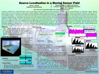
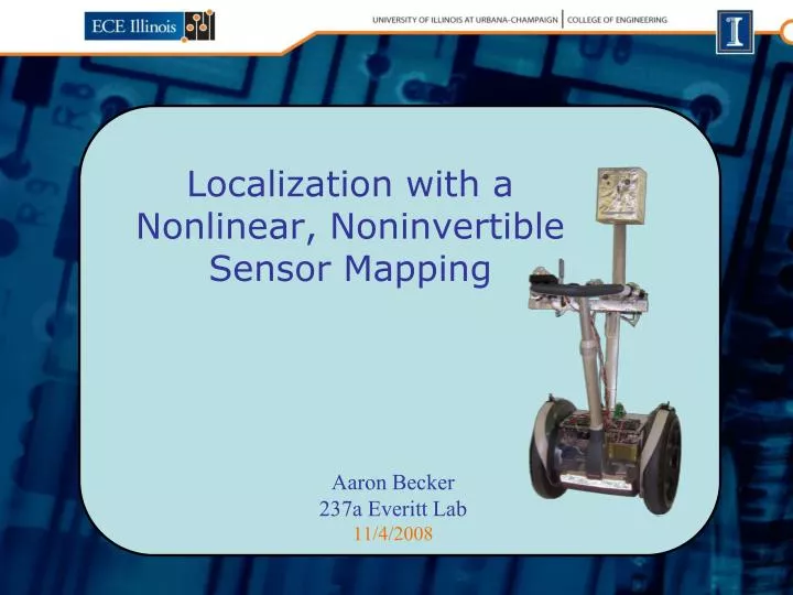
Localization with a Nonlinear, Noninvertible Sensor Mapping. Aaron Becker 237a Everitt Lab 11/4/2008. Problem statement System model Sensor model State estimator Results. Overview. Related Work. Localization via triangulation

E N D
Localization with a Nonlinear, Noninvertible Sensor Mapping Aaron Becker 237a Everitt Lab 11/4/2008
Problem statement System model Sensor model State estimator Results Overview
Related Work Localization via triangulation • (GPS) P. Enge and P. Misra, “Special issue on GPS: The global positioning system,”, 1999. • (IR signals) R. Want, A. Hopper, V. Falcao, and J. Gibbons, “The active badge location system,” 1992. • (Ultrasonic & RF) N. Prijantha, A. Chakraborty, and H. Balakrishan, “The cricket location-support system,” 2000. • (RF signals) T. W. Christ, P. Godwin, and R. Lavigne, “A prison guard duress alarm location system,” 1993. Map-based localization • (LIDAR & ceiling image) S. Thrun, M. Bennewitz, W. Burgard, et. al, “Minerva: A second generation museum tour-guide robot,” 1999. • (Light intensity) N. Ravi and L. Iftode, “Fiatlux: Fingerprinting rooms using light intensity,” 2007. • (GSM and K-NNSS fingerprinting) V. Otsason, A. Varshavsky, A. LaMarca, and E. de Lara, ”Accurate GSM indoor localization,” 2005. WiFi localization • (NNSS) P. Bahl, V. Padmanabhan, and A. Balachandran, “A software system for locating mobile users,” 2000. • (Blueprints and transmitter locations) M. Robinson and I. N. Psaromiligkos, “Received signal strength based location estimation of a wireless LAN client,” 2005. • (Gaussian Processes) B. Ferris, D. Hahnel, and D. Fox, “Gaussian processes for signal strength-based location estimation,” 2006.
System Model Derivation of control inputs
State update equation: System Evolution
Objective • At all times, have a state estimate close to the true state • Minimize the current expected squared error
Dead Reckoning Dead Reckoning True Position • Causes of Drift • Model errors • Process noise
Maximum Received Signal Strength in Everitt Lab Commercial scan, January 2008
Sensor Model Prediction algorithm
Often we have fewer sensors than states or sensors that do not return our state directly State Estimation – Observers without Probability –
State Observer Example With feedback we can ‘estimate’ our state We can design our observer to converge to the correct state at any rate if system is: Stable Observable Linear
Bayesian Propagation Link to Algorithm
The Kalman filter is the optimal linear estimator The robotic system is nonlinear System can be linearized We will still have the best linear estimator at the estimated operating point Extended Kalman Filter – Dealing With Nonlinearities EKF algorithm
We can approximate any probability distribution with samples (particles) Particle Filter • Particle filters can represent multimodal distributions:
Particle Filters in Action Initialization Here, a uniform distribution is approximated (blue) Global sensors are used to weigh the particles And the distribution is resampled (red)
Here, a distribution is propagated (blue) And then the distribution is resampled (red) Particle Filters in Action Step Global sensors are used to weigh the particles, along with the C_space
The SegMonster can localize and track itself in the hallways of Everitt Lab Results
Video Of Particle Filter True Position Dead Reckoning Particle Filter 95% Confidence Ellipse (+/-2 std)
Video of Particles Propagate Update
Questions • Dead reckoning: velocities from encoders • Nonlinear observer example • Bayesian methods: • Continuous • Discrete • Particle filtering: • Block diagram • Motion model • SegMonster • Dynamics • Improvements • Potential fields • Multimodal distributions • Wireless mapping (outdoors) • Adaptive Control: parameter estimation/RWP
Assumption: our probability is normally distributed Implication: position can be represented with just the mean and covariance Observing With Probability Distributions
Has high dependence on initial conditions (open loop) Dead Reckoning • One of Igor's former masters had made a tick-tock man, all levers and gearwheels and cranks and clockwork. Instead of a brain, it had a long tape punched with holes. Instead of a heart, it had a big spring. Provided everything in the kitchen was very carefully positioned, the thing could sweep the floor and make a passable cup of tea. If it wasn't carefully positioned, or if the ticking, clicking thing hit an unexpected bump, then it'd strip the plaster off the walls and make a furious cup of cat. • Thief of Time, Terry Pratchet
Bayesian Filters Return to presentation
Discrete Bayesian Filter Two Steps to propagate belief Return to Questions
Particle Filter Block Diagram Return to Questions
Propagates one sample (do this to each sample): State Estimation Cookbook
Tuning Parameters α1,α2,α3,α4 Effect of Propagation Parameters Left: [0.005, 0.001, 0.46, 0.02] Right: [0.01, 0.005, 0.0016, 0.02]
Calculating Errors Return to Questions
Assumes w[i]k is normalized (sums to 1) and that you have calculated the means for x and y, How to calculate Covariance from particles Return to Questions
The particle filter can represent multimodal distributions, but the covariance and mean are now meaningless statistics. k-means algorithm to find k means, and choose the mean with the highest probability (or highest average probability) Better: use Expectation Maximization algorithm to identify most probable point. How to deal with a Multimodal probability distribution Return to Questions
Equations of motion, differential drive robot [Steve M LaValle, Planning Algorithms pg 728 http://planning.cs.uiuc.edu/, 13.1] Generating Velocities from Encoders Return to Presentation
The objective for the design of the SegMonster was to produce a low cost robotic platform built to handle both indoor and outdoor environments that could move at the speed of a jogging human. These design objectives resulted in a non-destructive addition to a standard Segway that exhibited a certain level of autonomy. Specifically, the SegMonster could follow a sidewalk by using a color camera to segment between grass and concrete, and follow another SegWay by tracking a red LED array attached to the lead Segway. The SegMonster was equipped with a single IR sensor to detect obstacles immediately in front of it and programmed to stop until the obstacle was removed. This level of autonomy can be called 'behavior level', since the SegMonster relied entirely on local data (wheel encoders, and the IR sensor) or calculated a local control law based on the immediate inputs (using the camera to determine whether the robot was close or far from the sidewalk edge, or visual servo-ing based on the size and location of a red color blob segmented from the camera). The SegMonster did calculate a position estimate directly from wheel encoder data, which was reasonably accurate for paths of length less than 20 feet. We were able to use this data to move the SegMonster in a 5’x5’ box pattern. Though the SegMonster had one global sensor (the camera), it was used entirely for local based control. The first controller for the Segmonster used classical techniques – inner PID control loops for each motor, and outer loop velocity based PI loops for the reference body angle and turning angle. Enabling the SegMonster to carryout complex tasks, a global position estimate is necessary SegMonster Dynamics
Moves by tilting forwards/backwards The SegMonster
Comparison to inverted pendulum • θ is angle from vertical • ℓ length to Center Of Mass • MC is mass of cart • Mp mass of pendulum • I inertia of pendulum • x horizontal displacement • of cart
Cart and Pendulum forces can be calculated separately • The cart cannot move in vertical direction, so • Sum forces on FBD of cart in horizontal direction: • Sum forces on pendulum in horizontal direction • Sub second equation in for N:
Forces perp to pendulum To remove Pan N, sum the moments about the COM of the pendulum Sub (2) into (1) Group angular accelerations Divide by mass of pendulum Isolate horizontal acceleration Simplify Near the equilibrium position, with small angular accelerations, the horizontal acceleration is fixed Forces perpendicular to pendulum
Offset of pivot force Constant gravity on handle Offsetx = 2.25” Offsety = 8.25” Equations not entirely accurate