Download
1 / 35
350 likes | 354 Views
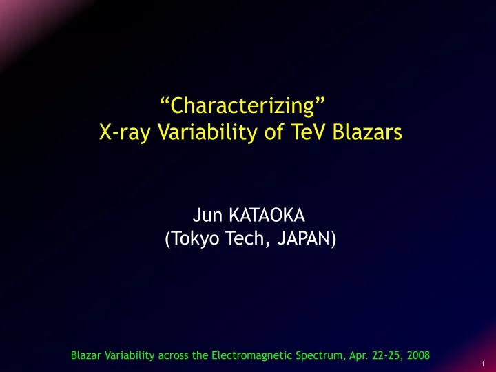
“Characterizing” X-ray Variability of TeV Blazars. Jun KATAOKA (Tokyo Tech, JAPAN). Blazar Variability across the Electromagnetic Spectrum, Apr. 22-25, 2008. Outline. X-ray observations of TeV blazars. Spectral evolution. Variability (short/long), time lag++.

E N D
“Characterizing” X-ray Variability of TeV Blazars Jun KATAOKA (Tokyo Tech, JAPAN) Blazar Variability across the Electromagnetic Spectrum, Apr. 22-25, 2008
Outline • X-ray observations of TeV blazars • Spectral evolution • Variability (short/long), time lag++ • Analysis tools for characterizing variability • Normalized Power Spectrum Density (NPSD) • Structure Function (SF) • Discrete Correlation Function (DCF) ... w/ detailed MC simulations • Recent news from Suzaku • Summary
Extragalactic VHE sources • 19 VHE emitters – mostly blazars • except for a radio galaxy M87. • Most TeV blazars are nearby (z < 0.2) • HBLs, but two exceptions. • - BL Lac … LBL • - 3C 279 … QHB at z = 0.536!
Why TeV blazars in X-ray? Suzaku MAGIC QHB LBL HBL Inverse Compton Synchrotron Kubo+ 98, Fossati+ 98, JK 02 Takahashi+ 08 • Probing the jet physics at very end of electron acceleration: gmax. • Expecting a large amplitude, short time-scale variability. • Multiband correlation - correlated or isolated (orphan) flares often • reported in X-ray and TeV bands.
65 60 55 50 45 40 35 XIS 0.6~10keV count/sec PIN 12~40keV 1.6 1.4 1.2 count/sec 1 0.8 0.6 0 10000 20000 30000 40000 50000 60000 70000 80000 (0day) (0.5day) (1day) time [sec] e.g., Mrk 421 with Suzaku • X-ray spectral evolution within a few ksec up to ~ 40 keV. • An overall trend that the peak energy (Epeak) and peak flux (nFn,peak ) • increase or decrease together. Mrk 421 Ushio+ 08 in preparation
X-ray Variability – daily flare Int. shock Mrk 421 (1998) Non-thermal emission Gfast Gslow collision (shock) • Daily flare suggests R ~ c tvar d ~ 10-3 pc. • Only little variability on tvar << 1d : “Internal shock” • Modulation of relativistic outflows - faster shell catches up with • the slower one at D ~ 10 Gjet2 Rg ~ 103 Rg ~ 0.01 pc sub-pc jet (the first site of E-dissipation)
X-ray variability – time lag (1) Takahashi+ 96 Low (0.5-1.5keV) cts/s High(1.5-7.5keV) Mrk 421 High/Low 0 0.5day 1day • Time-lag in the LCs has been claimed for several TeVblazars. • (e.g., Takahashi+ 96,98, Chiapetti+ 99, Zhang+ 99, JK+ 00) Energy dependence of electron cooling time? : Tsync B-3/2 E-1/2 • Other groups voiced concerns about the reality of time-lag that are • smaller than orbital periods (~ 6ks)of satellites. (e.g., Edelson et al. 01)
X-ray variability – time lag (2) +2000s lag 0 -2000s Perigee 7000 km Apogee 114000 km Inclination 40 deg Orbital period 48 hr cts/s Mrk 421 0 0.2day 0.4day 0.6day Brinkmann+ 03, 05 • High eccentric orbit of XMM-Newton provided uninterrupted, • high sensitivity data most suitable for detailed temporal studies. Lags of both signs, up to ± 2000 sec. • HOWEVER, large amplitude variability has not been observed yet, • over ~0.8 day observations (only ±10 % variation).
X-ray Variability – long-term (1) mCrab 1day 7day Mrk 421 RXTE-ASM (2-10 keV) Sensitivity: 15 mCrab @ 1day Distance (light year) • Unfortunately, even the brightest src like Mrk 421 is difficult • to be detected with RXTE-ASM for 1-day accumulation of data.
X-ray Variability – long-term (2) JK+ 01 #7 #3 #1 #2 #6 #2 #3 #5 #4 #5 #6 #1 #4 #7 • Modern X-ray astronomy satellite is good at pointing observations, • but not suitable for continuous monitoring. • Highly under-sampling data! How to characterize variability? • What about the periodic “orbital gap” ? Main topic of this talk.
Normalized PSD analysis Miyamoto+ 95, Hayashida+ 98 f0.5 f-0.9 f-1.9 f-1.5 Fj : source count rate at tj T : data length of time series Fav: mean of F • Similar to an usual PSD, but less affected by window sampling. If the LC contains a time gap, the NPSD is calculated for each segments before/after the gap, and take their average. • Similarity of the PSD between the Gal.BHs and Seyferts. An efficient way of BH mass estimation (e.g., Hayashida+ 98)
TeV blazars: observed LC & PSD JK+ 01 ~f-1 Mrk 421 Mrk 501 ~f-2.5 PKS2155 • Strong red noise: P(f) f-2.5 with fbrk ~ 10-5 Hz. Note, for Sy (1) variability is faster : fbrk, Sy ~ a few x104 Hz (2) PSD index is a bit flatter : Psy(f) f-1.5~ 2 • How about the reality of this finding? need careful simulation!
MC simulation: method • Assume that the PSD of the source (e.g., TeVblazar) is • expressed by a convex broken power-law of the form: fb: break frequency (tb~ 1/fb: characteristic timescale) • Using a Monte Carlo simulation, we generate a set of random • numbers, uniformly distributed between 0 and 2 p, and use them • for the phase of each Fourier component of the assumed PSD. • By a Fourier transform of this Monte Calro generated periodogram, • we obtain a light curve of certain # of bins lengths, which covers • the total span of the observation. C(t) = (1/2p)SfP(f)1/2 e-2pift
MC simulation: ex.(1) • An example of how the LC looks like for the different choice of • the PSD index from -1.0 (i.e., fractal) to -3.0 (strong red type). • Small fluctuation large amplitude variations.
MC simulation: ex.(2) • Example cases for f-2.5 and fb = 10-5 Hz: • Close similarity to the observed LC in TeV blazars. • Note “wide variety” of the LC even if assuming the same PSD.
MC simulation: Orbital Gap • To mimic the observed LC, the same sampling window • (orbital gap of ~ 5760 s) was applied to the simulated LC. • By using more than ~ 1000 MC simulated LC, we confirm that the • NPSD actually minimize the effects caused by sampling window. orbital gap Simulation #1~ #10
Structure function analysis Simonetti+ 85, JK+01, Tanihata+03 some a(t): a point of the LC t : time separation N : # of pairs ~ t0.5 But when the quality of each data are non-uniform; weight factor • Firstly introduced to study flicker of extragalactic radio sources. • While in theory the SF is completely equivalent to traditional PSD, • it has several significant advantages: (1) much easier to calculate! (2) less affected by gaps in the LC, even if it is non-uniform.
SF: characteristics Paltani+ 99 t0 tb t2 ~2e2 • Reg 1 : A plateau due to the measurement uncertainty e. • Reg 2 : SF increases as t2 as long as t < Tmin. • Reg 3 : SF increases as tb(0 <b< 2) between Tminand Tmax. • Empirically, b a- 1 (a : PSD index) • Reg 4 : For t > tmax , the SF flattens again
TeV blazars: observed SF JK+ 01, Tanihata+ 03 Mrk 421 Mrk 501 Mrk 501 PKS2155 Mrk 421 PKS2155 t (ksec) • Strong red noise: SF(t) t1.5 with tb ~ 0.5 -3 day. • Consistent with what has been implied from the NPSD analysis • Reality of complicated features at t ~ tmax ?
MC simulation of the SF artifacts? Mrk 421 Observed Simulation • Simulated LCs (P(f) f-2.5 , fb = 10-5 Hz) well reproduce the • observed SF, but large uncertainty due to the finite length of • data if t ≳ 1/3 tmax. • Take special care about possible “artifacts” near tmax .
Warning – a case in literature Zhang+ 02 Be careful about this kind of “over-simplification”! PKS 2155-304
Long-term variability: observed JK+ 01 observed observed • Too sparse, unevenly sampled data prevent the analysis using • “most common” Fourier technique (e.g., NPSD). • The SF seems to be much better, but obviously Important to know • how the observed window affect the calculated SF.
Long-term variability: simulation JK+ 01 • Actually, MC simulation of the LCs by applying same sampling • window provides various spurious structures in the SF!
How to “robustly” evaluate the SF? Iyomoto+ 00, JK+ 01 • Based on a set of 1000 fake LCs, • we can compute the expected • mean value <SFsim (t)> and • variance ssf(t) at each t, for an • assumed PSD. • To evaluate the goodness of fit , • we calculate the sum of squared • difference: PL index a c2 map • We then generate other sets of • 1000 simulated LCs and fake SFs • to evaluated the distribution of • c2sim values. X break: tb
Importance of Monitoring Obs. Takahashi & JK 00 t0.3 t1.4 • Mrk 421 is the only TeVblazar for which RXTE-ASM always detect • its signal at > 4 s level, if 7-day accumulationof data. • Well-defined SF confirm the presence of characteristic time, but • also another variability component at t ≳ 10 day. GLAST, MAXI monitoring important!
MAXI: Monitor of All-sky X-ray Imaging • MAXI is an X-ray all-sky monitor on • the Japanese Experimental Module • (JEM) of the ISS, to be launched • in 2009.3. • Sensitivity ~ 5 times better than • RXTE-ASM, ~ 1mCrab @ 1week. See, more details: http://www-maxi.tksc.nasda.go.jp X-ray CCD Camera (SSC) 0.5-10 keV Gas Slit Camera (GSC) 2-30 keV
Underlying Physics? Perturvation in jets, including accel, cooling, R/c? (beamed) t1.4 Time variation of accreting flow ? (non-beamed) t0.3 • Surely two components exist in the variability of TeVblazars • - the one due to the perturbation produced in the jet, and the other • is due to time variation of accreting matter near the central BH. evenly sampled data awaited to test this speculation.
DCF analysis Edelson & Krolik 88 ai,bj: a point of data set {a},{b} a, b : means of {a} {b} sa, sb : standard deviation ea, eb : mesurement error • Firstly introduced to test variability correlation of optical • continuum and Hbflux. • Specifically designed to analyze unevenly sampled data. • Relatively easy to calculate by using all data points available. • Does not introduce new errors through interpolation.
ex1: a case of PKS2155-304 JK+ 00 D 3-8 keV vs 0.5-1 keV +4 ks DCF amplitude -1 0 +1 Time lag (day) • During the flare, change in the hard X-ray flux led the change in • the soft X-ray flux by ~ 4 ksec, similar to the case of Mrk 421. • The energy dependent time-lag is consistent with the differential • Sync cooling time, if B ~ 0.1 G (tcool B-3/2 E-1/2d-1/2). … but, could be artifacts ??? ( orbital gap ~ 6ksec)
Again, MC simulation! w/o orbit gap w/ orbit gap w/ orbit gap w/o orbit gap • Simulating thousand pairs of LCs, one is artificially shifted by • ~ 4 ksec to mimic the observed LC. • Although periodic gaps introduce larger uncertainties, lags on • ~ 4 kseccannot be the result of periodic gaps. e.g., Tanihata+ 03, Zhang+ 04
ex2: a case of 1ES1218+304 See poster by R.Sato 4-10 kev vs 0.4-1keV -20ks 4-10 keV 2-4 keV 1-2 keV 0.4-1 keV • Opposite sense of time-lag was clearly detected, with the maximum • “hard-lag” of ~ 20 ksec - much larger than orbital gap! • A wide variety of flare shape measured at different energies, • suggesting energy dependence in the rise/fall time-scales.
Direct fit of the “flare shape” Sato+ 08 ApJL (astro-ph/0804.2529) tacc tcool (i) Low energy • Rapid rise & slow decay • Asymmetric LC 0.3-1keV tacc tcool (ii) High energy • Slow rise & fast decay • Symmetric LC (tacc~tcool) 5-10keV • “rise time” ~ tacc & “fall time” ~ tcool • tacc (E) = 9.7×10⁻² (1+z)3/2x B-3/2d-3/2 E1/2 B = 0.049 x5 G (x5 : Gyro factor) • tcool (E) = 3.0×10³ (1+z)1/2 B-3/2d-1/2 E-1/2
Comparison w/ SED Sato+ 08 ApJL (astro-ph/0804.2529) Suzaku MAGIC γmin1.0 B 0.05 G Ue 8.3×10⁻³ erg/cm3 γbrk8×103 R 8×1016 cm UB 8.8×10⁻⁵ erg/cm3 γmax8×105d 20.0 Ue/UB 94 α -1.7 z 0.182 Very consistent with LC!
Summary: I have overviewed the sync X-ray variability of blazars and detailed temporal technique to evaluate the LCs. • Temporal techniques, such as PSD, SF, DCF are indeed powerful • tool, but special care must be taken if • (1) the data are not well sampled and • (2) short compared to the variability timescale of the system. • MC simulation is one of the best way to evaluate the effects • caused by sampling window and finite length of data. • If evaluating properly, the LC provides independent and/or • complementary information to the X-ray spectrum of TeV blazars.