Download
1 / 15
150 likes | 359 Views
Coherent X-ray Diffraction (CXD) X-ray imaging of non periodic objects. INTRODUCTION Why coherent X ray diffraction (CXD )? THE CXD TECHNIQUE Limits on the experimental setup arising from sampling and coherence Phasing of diffuse scattering: image reconstruction APPLICATIONS

E N D
Coherent X-ray Diffraction (CXD) X-ray imaging of non periodic objects
INTRODUCTION • Why coherent X ray diffraction (CXD)? • THE CXD TECHNIQUE • Limits on the experimental setup arising from sampling and coherence • Phasing of diffuse scattering: image reconstruction • APPLICATIONS • Examples of image reconstruction from CXD • Our plans, new experiments (?) • LIMITATIONSAND PERSPECTIVES • Dose and flux limitations • Femtosecond CXD • SUMMARY
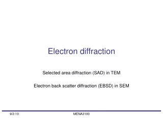
INTRODUCTION Why coherent X ray diffraction (CXD)? The rapid growth of nanoscience (“the next industrial revolution”) has produced an urgent need for techniques capable of revealing the internal structure, in three dimensions, of inorganic nanostructures and large molecules which cannot be crystallized. Scanning probe methods: limited to surface structures Electron microscope: provide atomic resolution images of projections of crystalline materials in thicknesses up to about 50nm, or tomography of macromolecular assemblies and inorganics at lower resolution.
THE CXD TECHNIQUE • the sample is illuminated by monochromatic coherent x-rays and a recording is made of a single diffraction pattern (for 2D) or a tilt series (for 3D); • phasing diffuse scattering • the unknown object is recovered by Fourier inversion. Within sample volume V there are N = V/ΔV volume elements. In a coherent scattering experiment, when all volume elements scatter inphase, F(Q) = NS(Q), and, when half of the volume elements scatter out-of-phase with respect to the other half, F(Q) = 0 (for identical volume elements). This gives rise to a typical `speckle‘ pattern.
Limits on the sample size arising from samplingand coherence Sampling: The Shannon interval for frequency-space sampling of the intensity is This corresponds to surrounding the electron density of the sample with a non-density region More generally, we can define the oversmpling ratio as The Shannon frequency becomes And the sample-detector distance (L) is given by where dpix is the detector-plane increment.
Beam coherence The oversampling method is strongly correlated with the coherence of the incident x rays. The higher the oversampling degree, the finer of the correspondingly features of the diffraction pattern have to be recorded faithfully, and hence the larger the coherence length of the incident beam needs to be. The required spatial and temporal coherence of the incident x rays are related to the oversampling degree by where Res is a desired resolution, and Δθ the divergence angle of the incident x rays.
Phasing of diffuse scattering: image reconstruction • Successful phase retrivial methods for non-periodic objects: • Gerchberg-Saxton-Fienup HiO algorithm (Fienup, 1982, 1987); • techniques based on analyticity and complex zeros (Liao et al., 1997); • (c) the study of projections onto convex sets (Bautschke et al., 2002); • the transport of intensity equations (Paganin & Nugent, 1998); • (e) direct methods, for real and positive objects (Spence et al., 2003, Carrozzini et al., 2004)
APPLICATIONS Reconstruction of non-periodic array of gold balls of 50 nm diameter SEM image of a random set of gold balls of 50 nm diameter at 550 eV. Experimental soft X-ray transmission diffraction pattern Recovered charge density using the modified SIR2002 program. B. Carrozzini et al., Acta Cryst. A60, 331, (2004)
3-D Imaging of non-crystalline structure at 50-nm resolution (a) SEM image of a double-layered sample made of Ni (~2.7 x 2.5 x 1µm3) (b) Coherent diffraction pattern from (a) (d) Iso-surface rendering of the reconstructed 3D structure (c) Reconstructed image from (b) Miao et al., Phys. Rev. Lett. 89, 088303 (2002)
Imaging whole Escherichia coli bacteria (A) diffraction pattern from E. coli bacteria displayed in a logarithmic scale. The dense regions inside the bacteria are likely the distribution of proteins labeled with KMnO4. The semitransparent regions are devoid of yellow fluorescent proteins. (B) An image reconstructed from (A) Miao et al., Proc. Natl. Acad. Sci. USA 100, 110 (2003)
LIMITATIONSANDPERSPECTIVES Dose and flux limitations: fluence (total photons per unit area) and dose (absorbed energy per unit mass) required to make a 3D CXD image at given resolution
Femtosecond CXD: beyond the radiation-damage limit: A way of overcoming the radiation damage limit in x ray imaging is to use pulses of x-rays that are shorter in duration than the damage process itself.