Download

1 / 111
1.24k likes | 1.44k Views
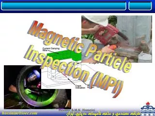
Magnetic Particle Inspection TWI. Magnetism. Some natural materials strongly attract pieces of iron to themselves. Such materials were first discovered in the ancient Greek city of Magnesia. Magnets were utilised in navigation. Oersted found a link between electricity and magnetism.

E N D
Magnetism • Some natural materials strongly attract pieces of iron to themselves. • Such materials were first discovered in the ancient Greek city of Magnesia. • Magnets were utilised in navigation. • Oersted found a link between electricity and magnetism. • Faraday proved that electrical and magnetic energy could be interchanged.
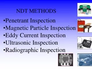
Magnetic Particle Inspection(MT or MPI) • MT is a test method for the detection of surface and near surface defects in ferromagnetic materials. • Magnetic field induced in component • Defects disrupt the magnetic flux causing “flux leakage”. • Flux leakage can be detected by applying ferromagnetic particles
Permeability (μ) • Permeability can be defined as the relative ease with which a material may be magnetised. • It is defined as the ratio of the flux density (B) produced within a material under the influence of an applied field to the applied field strength (H) • μ =B/H
Permeability (μ) • On the basis of their permeability materials can be divided into 3 groups: • Diamagnetic • Paramagnetic • Ferromagnetic
Permeability (μ) Diamagnetic: Permeability slightly below 1, weakly repelled by magnets. Examples: Gold, Copper, Water • Paramagnetic: Permeability slightly greater than 1, weakly attracted by magnets. • Examples: Aluminium, Tungsten Ferromagnetic: Very high permeability, strongly attracted by magnets. Examples: Iron, Cobalt, Nickel
Domain theory • A domain is a minute internal magnet • Each domain comprises 1015 to 1020 atoms N-S N-S N-S N-S N-S N-S N-S N-S N-S N-S N-S N-S Unmagnetized state Domains randomly orientated
Domain Theory N-S N-S N-S N-S N-S N-S N-S N-S N-S N-S N-S N-S Magnetized state Domains orientated in external magnetic field N-S N-S N-S N-S N-S N-S N-S N-S N-S N-S N-S N-S
Domain Theory N-S N-S N-S N-S N-S N-S N-S N-S N-S N-S N-S N-S Saturated state All domains orientated in strong external field N-S N-S N-S N-S N-S N-S N-S N-S N-S N-S N-S N-S
N-S N-S N-S N-S Un-magnetised N-S N-S N-S N-S N-S N-S N-S N-S
N-S N-S N-S N-S Un-magnetised N-S N-S N-S N-S N-S N-S N-S N-S N-S N-S N-S N-S N-S N-S Magnetised N-S N-S N-S N-S N-S N-S
N-S N-S N-S N-S Un-magnetised N-S N-S N-S N-S N-S N-S N-S N-S N-S N-S N-S N-S N-S N-S Magnetised N-S N-S N-S N-S N-S N-S Saturated N-S N-S N-S N-S N-S N-S N-S N-S N-S N-S N-S N-S
N-S N-S N-S N-S Un-magnetised N-S N-S N-S N-S N-S N-S N-S N-S N-S N-S N-S N-S N-S N-S Magnetised N-S N-S N-S N-S N-S N-S N-S N-S N-S N-S N-S N-S Saturated N-S N-S N-S N-S N-S N-S N-S N-S N-S N-S N-S N-S Residual N-S N-S N-S N-S N-S N-S
S N Lines of Flux
Lines of flux • By convention they flow from North to South outside and South to North inside • They form closed loops • They never cross • They follow path of least resistance • Flux density is the number of lines of flux passing through a unit area. • Field strength is highest where where flux density is highest.
Electromagnetism + _ • A current flows through a conductor and sets up a magnetic field around it • Field is at 90o to the direction of the electrical current Direction of current flow Direction of magnetic field
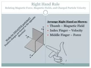
Right Hand Rule Field Current + Right Hand Rule _
Coil Magnetisation _ + S N • Changes circular field into longitudinal • Increases the strength of the field
Hysteresis Place an un-magnetised piece of ferromagnetic material within a coil Saturation point B+ Virgin curve H + H - B-
Hysteresis B + Residual magnetism H - H + H + B -
Hysteresis B+ H - H + H + Coercive force B -
Hysteresis B + H - H + H + Negative saturation point B -
Hysteresis A B C F E D
Hysteresis Hard ferromagnetic Soft ferromagnetic
Permeability (µ) • The ease with which a material can be magnetised • Opposite of reluctance (difficulty with which a material can be magnetised) • µ = B / H • Permeability of free space = µo • Relative Permeability (µr) = µ / µo
Relative Permeability (µr) • Paramagnetics Slightly > 1 • Diamagnetics Slightly < 1 • Ferromagnetics 240 +
Typically Low carbon steel High permeability Easy to magnetise Low residual magnetism Typically high carbon steel Lower permeability More difficult to magnetise High levels of residual magnetism Hard v Soft Ferromagnetics Soft Hard
Definitions • Magnetic field Region in which magnetic forces exist Flux Total number of lines existing in a magnetic circuit Flux Density Magnetic flux per unit area (measured in Tesla)
Principle of MPI : Flux Leakage No Defect Defect N S N S Lines of flux follow the path of least resistance
MAGNETIC SATURATION LEAKAGE FIELDS
Visibility of Flux Leakage Depends on: • Depth of defect • Orientation of defect shape of defect • Size of defect • Permeability of material • Applied Field Strength • Contrast
Indications Relevant Indications - Indications due to discontinuities or flaws Non-Relevant Indications - Indications due to flux leakage from design features Spurious Indications - Indications due incorrect inspection procedures
Defect Orientation N S Defect at 90 degrees to flux : maximum indication
Defect Orientation N S >30 Degrees to Flux: Acceptable indication
Defect Orientation N S <30 Degrees to Flux : Weak indication
Defect Orientation Field Field Field Field N N N S S S Field Field Test 1 Test 2 MPI requires 2 tests at 90o to one another
Permanent Magnet N S Longitudinal field between poles Maximum sensitivity for defects orientated at 90º to a line drawn between poles
Advantages No power supply No electrical contact problems Inexpensive No damage to test piece Lightweight Disadvantages Direct field only Deteriorate over time No control over field strength Poles attract detecting media Tiring to use Permanent Magnet
Electromagnetism + _ • A current flows through a conductor and sets up a magnetic field around it • Field is at 90o to the direction of the electrical current Direction of current flow Direction of magnetic field
Coil Magnetisation _ + S N • Changes circular field into longitudinal • Increases the strength of the field
Electromagnets Maximum sensitivity for defects orientated at 90º to a line drawn between the poles Magnetic Field Induced in Core by Electric Current Passed Through Coil Soft Iron Laminated Core Adjustable Legs & Pole Pieces
Advantages AC,DC or rectified Controllable field strength No harm to test piece Can be used to demagnetise Easily removed Disadvantages Power supply required Longitudinal field only Electrical hazard Poles attract particles Legs must have area contact Electromagnets
Prods • Current passed between 2 contacts. • Defects detected parallel to contacts Field Current Defects
Advantages AC,DC or rectified Controllable field strength No poles attract particles Control of amperage Disadvantages Arcing / damage to work piece Transformer required Current can be switched on without creating field Good contact required 2 man operation Prods
Flexible Cable • Flexible, current carrying cable Used as • Adjacent cable • Threading cable • Flexible coil
Advantages Simple to operate No danger of burning AC,DC or rectified Current adjustable Disadvantages Difficult to keep cables in place High currents required Transformer required Flexible Cable
Current Flow Defects Current Circular Field Current passed through sample
Threading Bar • Current passed through brass bar placed between heads of bench unit • Circular field generated around bar • Sample hung from bar