Download
1 / 36
360 likes | 366 Views
MGS-550 Product Portfolio. Performance. Price. HGM-MZ. MGS-550 GP. MGS-550 XP. MGS-250 IR. MGS-150 IP41. MGS-150 IP66. IAM-100. MGD-100. MGS-550 A new Family of Transmitters. One user interface for all sensing technologies from Bacharach Electrochemical Catalytic Bead Infrared

E N D
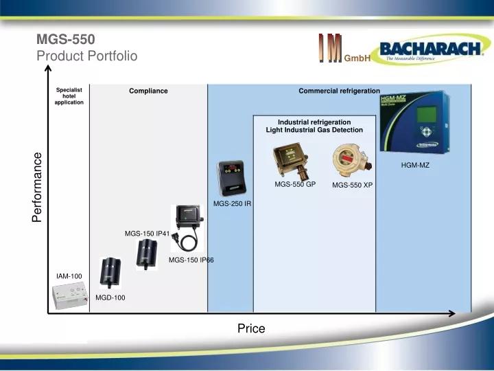
MGS-550Product Portfolio Performance Price HGM-MZ MGS-550 GP MGS-550 XP MGS-250 IR MGS-150 IP41 MGS-150 IP66 IAM-100 MGD-100
MGS-550A new Family of Transmitters • One user interface for all sensing technologies from Bacharach • Electrochemical • Catalytic Bead • Infrared • Semiconductor • One concept for all applications • two housing styles: ABS IP 66 and aluminum explosion proof • Simplicity without sacrificing functionality
MGS-550A new Family of Transmitters • One user interface for all family members • 5 digit, 7-segment LED, 3 Status LEDs • Magnetic wand and push buttons • Simple, single level menu structure • Analog and digital signal output • Three on-board relays (user to designate, e.g. A1, A2, Fault) • Electrical ratings • 19.5 to 28.5 VDC or 24 VAC ± 20% • 4 to 20 mA, 0 to 5 V, 1 to 5 V, 0 to 10 V, 2 to 10 V – user selectable • Modbus RTU via RS 485 • Relays 1 A @ 24 VDC/VAC, 0.5 A @ 125 VAC
MGS-550ATEX, IECEx Approvals, XP-version • MGS-550 XP electronics enclosure • II 2G Ex d IIC Gb • MGS-550 XP sensor enclosure • II 2G Ex d IIC T4 Gb, -20 ≤ Tamb ≤ +60 ºC • Each enclosure has its own approval. • However, the combination has not been submitted.
MGS-550General Purpose • Four types of instruments • One local sensor: • 5 digit, 7 segment LED display • 3 status LEDs • 4 magnetic switches and push buttons • 2 wires for power • 2 wires for analog output (4 if redundant) • 2 wires for digital output • 3 SPDT relays; independent to designate Un-used ports can be plugged. Plugs and cable glands are supplied.
MGS-550General Purpose • Four types of instruments • One remote sensor: • 5 digit, 7 segment LED display • 3 status LEDs • 4 magnetic switches and push buttons • 2 wires for power • 2 wires for analog output (4 if redundant) • 2 wires for digital output • 3 SPDT relays; independent to designate Un-used ports can be plugged. Plugs and cable glands are supplied. Order remote sensor separately.
MGS-550General Purpose • Four types of instruments • Two local sensors: • 5 digit, 7 segment LED display • 3 status LEDs • 4 magnetic switches and push buttons • 2 wires for power • 4 wires for analog output • 2 wires for digital output • 3 SPDT relays; independent to designate Un-used ports can be plugged. Plugs and cable glands are supplied. Order second sensor separately.
MGS-550General Purpose • Four types of instruments • One local and one remote sensor: • 5 digit, 7 segment LED display • 3 status LEDs • 4 magnetic switches and push buttons • 2 wires for power • 4 wires for analog output • 2 wires for digital output • 3 SPDT relays; independent to designate Un-used ports can be plugged. Plugs and cable glands are supplied. Order remote sensor separately.
MGS-550General Purpose • Four types of instruments • Two remote sensors: • 5 digit, 7 segment LED display • 3 status LEDs • 4 magnetic switches and push buttons • 2 wires for power • 4 wires for analog output • 2 wires for digital output • 3 SPDT relays; independent to designate Un-used ports can be plugged. Plugs and cable glands are supplied. Order remote sensors separately.
MGS-550Explosion Proof • Four types of instruments • One local sensor: • 5 digit, 7 segment LED display • 3 status LEDs • 4 magnetic switches and push buttons • 2 wires for power • 2 wires for analog output (4 if redundant) • 2 wires for digital output • 3 SPDT relays; independent to designate No cable glands are supplied with the instrument ! Two plugs are supplied.
MGS-550Explosion Proof • Four types of instruments • One remote sensor: • 5 digit, 7 segment LED display • 3 status LEDs • 4 magnetic switches and push buttons • 2 wires for power • 2 wires for analog output (4 if redundant) • 2 wires for digital output • 3 SPDT relays; independent to designate No cable glands are supplied with the instrument ! Two plugs are supplied. Order remote sensor separately.
MGS-550Explosion Proof R&D is still working on this solution. Elbow not supplied. • Four types of instruments • Two local sensors: • 5 digit, 7 segment LED display • 3 status LEDs • 4 magnetic switches and push buttons • 2 wires for power • 4 wires for analog output • 2 wires for digital output • 3 SPDT relays; independent to designate ? No cable glands or elbow are supplied with the instrument ! Two plugs are supplied. Order second sensor separately.
MGS-550Explosion Proof • Four types of instruments • One local and one remote sensor: • 5 digit, 7 segment LED display • 3 status LEDs • 4 magnetic switches and push buttons • 2 wires for power • 4 wires for analog output • 2 wires for digital output • 3 SPDT relays; independent to designate No cable glands are supplied with the instrument ! Two plugs are supplied. Order remote sensor separately.
MGS-550Explosion Proof • Four types of instruments • Two remote sensors: • 5 digit, 7 segment LED display • 3 status LEDs • 4 magnetic switches and push buttons • 2 wires for power • 4 wires for analog output • 2 wires for digital output • 3 SPDT relays; independent to designate No cable glands are supplied with the instrument ! Two plugs are supplied. Order remote sensors separately.
MGS-550Detectable Gases and Ranges O2 30 Vol% CO 1,000 ppm H2S 100 ppm NH3 100 / 1,000 / 5,000 / 10,000 ppm / 100 %LEL CO2 5,000 / 10,000 / 20,000 / 30,000 / 40,000 / 50,000 ppm Refrigerants 1,000 / 10,000 ppm Combustible Gases 5,000 ppm / 100 %LEL H2 5,000 / 10,000 ppm C2H4 2,000 ppm VOC 1,000 ppm Cl2 10 ppm F2 1 ppm HCl 10 ppm SO2 10 ppm NO2 20 ppm HCN 30 ppm O3 1 ppm
MGS-550 User Interface 5-digit, 7-segment red LED display Three status LEDs Four magnetic switches (both versions) Four push buttons on round Bezel
MGS-550Interface PCB Access to sensor connectors; power, communication and relay terminals. Use 16 to 20 AWG / 0.5 to 1.5 mm2 wires.
MGS-550 Gas Alarm Generation – Non-Latching Gas Level Alarm-On Level A1 Hysteresis = 5% of full scale Alarm-Off Level Alarm 1 State Fixed hysteresis to avoid chatter around the alarm set-point
MGS-550 Gas Alarm Generation – Non-Latching for Oxygen Fixed hysteresis to avoid chatter around the alarm set-point
MGS-550 Gas Alarm with ON Delay set A1 ON Delay Alarm 1 On ON Delay time selectable 0 to 15 minutes
MGS-550 Gas Alarm with ON Delay set A1 ON Delay Alarm 1 On Delay Reset If set, alarm condition must exist for at least the ON Delay time before an alarm is generated
MGS-550 Multiple Gas Alarms with ON Delay set A3 A2 A1 ON Delay 3 Alarm 3 On ON Delay 2 Alarm 2 On ON Delay 1 Alarm 1 On If set, alarm condition must exist for at least the ON Delay time before an alarm is generated
MGS-550 Gas Alarm with OFF Delay set – Non-Latching A1 OFF Delay Alarm 1 On OFF Delay time selectable 0 to 15 minutes
MGS-550 Gas Alarm with OFF Delay set – Non-Latching A1 OFF Delay Alarm 1 On If set, alarm condition must expire for at least the OFF Delay time before an alarm is reset
MGS-550 Gas Alarm with ON and OFF Delay set – Non-Latching A1 OFF Delay ON Delay Alarm 1 On If set, alarm condition must exist for at least the ON Delay time before an alarm is generated and expire for at least the OFF Delay time before an alarm is reset
MGS-550 Latching Gas Alarm A1 Acknowledgement Alarm 1 On A latching gas alarm stays on until it is acknowledged
MGS-550 Multiple Latching Gas Alarms A2 A1 Acknowledgement Alarm 2 On Alarm 1 On Latching gas alarms stay on until they are acknowledged
MGS-550 Acknowledgeable Gas Alarm and Timeout A1 Acknowledged Alarm 1 On Alarm 1 On Timeout An acknowledged gas alarm will be triggered again if the alarm condition still exists after the timeout has expired. Timeout selectable between 0 and 59 minutes.
MGS-550 Acknowledgeable Multiple Gas Alarms and Timeout A2 A1 Acknowledged Alarm 2 On Alarm 2 On Timeout Alarm 1 On Alarm 1 On Acknowledged gas alarms will be triggered again if the alarm conditions still exist after the timeout has expired
MGS-550 Acknowledgeable Multiple Gas Alarms and Timeout A2 A1 Acknowledged Alarm 2 On Timeout Alarm 1 On Alarm 1 On An acknowledged gas alarm will be triggered again if the alarm conditions still exist after the timeout has expired, whereas A2 will not be triggered again in this scenario.
MGS-550 Acknowledgeable Gas Alarm and Timeout A2 A1 Acknowledged Alarm 2 On Alarm 1 On Timeout Alarm 1 On An acknowledged gas alarm will be triggered again if the alarm condition still exists after the timeout has expired. Any other gas alarm will be triggered immediately once the condition exists.
MGS-550 Acknowledgeable Multiple Gas Alarms and Timeout Reset A2 A1 Acknowledged Acknowledged Alarm 2 On Alarm 2 On Timeout Reset Alarm 1 On Timeout Timeout Alarm 1 On Timeout An acknowledgement will reset a timeout. However, the gas alarm will be triggered again if the alarm conditions still exist after the new timeout has expired.
MGS-550 Acknowledgeable Gas Alarm and ON Delay A1 Acknowledged ON Delay Alarm 1 On An acknowledgement during the ON Delay time has no effect. The gas alarm will be triggered if the alarm condition still exists.
MGS-550 Acknowledgeable Gas Alarm and OFF Delay A1 Acknowledged Alarm 1 On An acknowledgement during the OFF Delay time will immediately reset the gas alarm.
MGS-550 Acknowledgeable A1 and Latching A2 A2 A1 Alarm 1 Acknowledged and Alarm 2 Latching Cleared Alarm 2 On Alarm 1 On An acknowledgement will reset the gas alarms and clear the latching configuration of alarm 2.