Download
1 / 23
230 likes | 241 Views
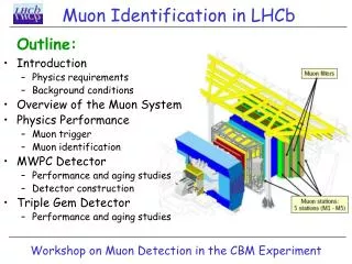
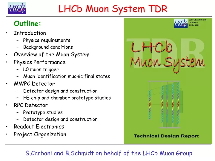
Outline: Introduction Physics requirements Background conditions Overview of the Muon System Physics Performance L0 muon trigger Muon identification muonic final states MWPC Detector Detector design and construction FE-chip and chamber prototype studies RPC Detector

E N D
Outline: Introduction Physics requirements Background conditions Overview of the Muon System Physics Performance L0 muon trigger Muon identification muonic final states MWPC Detector Detector design and construction FE-chip and chamber prototype studies RPC Detector Prototype studies Detector design and construction Readout Electronics Project Organization LHCb Muon System TDR G.Carboni and B.Schmidt on behalf of the LHCb Muon Group
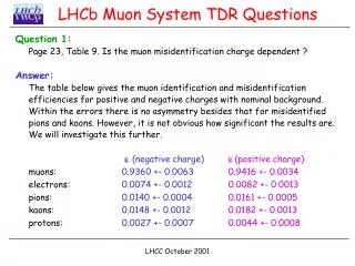
Physics Goals: The Muon system of LHCb is primarily used to trigger on muons produced in the decay of b-hadrons: b X ; In particular:B J/(+-) Ks ; Bs J/(+-) ; Bs +- The muon momentum is measured precisely in the tracking system The muon system identifies muons from tracks in the tracking system Requirements: Modest momentum resolution (~20%) for a robust PT -selective trigger Good time resolution (a few ns) for reliable bunch-crossing identification Good muon identification (~90%); small pion-misidentification (~1%) Introduction 0 0 0 B.Schmidt
Background sources in the LHC environment: ,K X decays main background for L0 muon trigger Shower particles hadron punch-through including shower muons Low-energy background induced by n- processes contributes significant to chamber hit rate Machine background, in particular high energy beam-halo muons Requirements: High rate capability of chambers Good ageing properties of detector components Detector instrumentation with sufficient redundancy Introduction B.Schmidt
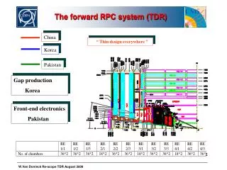
Overview • 5 Muon stations with • 2 independent layers/station • redundancy • Layers are logically ORed • high station efficiency • 435m2 of detector area • with 1380 chambers • Hadron Absorber of 20 • thickness M1 M2 M3 M4 M5 B.Schmidt
Level 0 Muon Trigger: Muon Trigger Algorithm • Muon track finding: • Find seed pad in station M3 • Find pads within opened search windows (FOI) in stations M2, M4 and M5 • Use pads found in M2 and M3 to extrapolate to M1 and find pad in M1 within FOI • Stations M1 and M2 are used for the PT-measurement • -> Muon Trigger exploits multiple scattering in the muon shield by • applying tight search windows B.Schmidt
Side view: Front view: (1 Quadrant of Station 2) Muon Detector Layout Total number of physical channels: ~120 k (TP: ~240k) Total number of logical channels: ~ 26k (TP: ~45k) -> Projectivity to interaction point B.Schmidt
Particle Rates and System Technologies • Procedure to determine particle rates: • LHCb peak Luminosity of 51032 cm2/shas been assumed • Safety factor of 5 has been applied for M2-M5 and 2 for M1 Required Rate Capability per cm2 Technology Choice • Technology Choice: • In the outer part of M4 and M5 a technology with a rate capability of 1kHz/cm2 • and cross talk of 20-50% can be used -> RPC, covers 48% of muon system • For most of the regions MWPCswith atime resolution about 3ns are the optimal • solution. -> MWPC, cover 52% of the total area • No technology chosen yet for the inner part of M1 ( <1% of total area). • Technologies under consideration: triple GEMs and asymmetric wire chambers B.Schmidt
Trigger Performance: TDR Muon system includes realistic chamber geometry and detector response -> TDR Muon System is robust -> Slight improvement in performance compared to the TP Muon System. Level 0 Muon Trigger B.Schmidt
Beam halo muons: Distribution of energy and radial position of halo muons 1m upstream of IP travelling in the direction of the muon system Muons entering the experimental hall behind M5 give hits in different BX in the muon stations -> No significant effect Halo muons are present in ~1.5% of the bunch crossings About 0.1% of them cause a L0 muon trigger Level 0 Muon Trigger B.Schmidt
Algorithm: Extrapolate reconstructed tracks with p > 3GeV/c and first hits in Velo from T10 to the muon system (M2 etc.) Define a field of interest (FOI) around extrapolation point and Define minimum number of stations with hits in FOIs M2+M3 for 3 p 6 GeV/c M2+M3+(M4 or M5) for 6 p 10 GeV/c M2+M3+M4+M5 for p 10 GeV/c Muon Identification B.Schmidt
Performance: Nominal Maximal background background p>6GeV/c Sx<0.053 94.00.3 94.30.3 90.00.6 Me 0.780.09 3.50.2 0.60.1 M 1.500.03 4.000.05 1.20.05 MK 1.650.09 3.80.1 1.20.1 MP 0.360.05 2.30.1 0.30.1 Additional cuts on slope difference Sx between tracking and muon system and pare required in case of large bkg. -> M ~ 1% ~ 90% Muon Identification B.Schmidt
B0 J/(+-) Ks: Well established CP-violating decay from which angle in the unitary triangle can be determined. J/ (+-) reconstruction: - oppositely charged tracks identified as muons. - Mass of dimuon pair consistent with J/ mass -> More than 100k ev./year expected in LHCb Bs +-: Decay involves FCNC and is strongly suppressed in the Standard Model -> BO mass resolution 18 MeV/c2 -> ~10 signal events over 3 bkg expected per year LO performance for both decays: L0 trigger acceptance of fully reconstructed events is 98%. L0 muon acceptance is 95% with>70% triggered by muon trigger alone. Muonic Final States 0 B.Schmidt
Overview: MWPC detector covers 52% of total area 864 chambers (up to 276/station) Same chamber height in all regions of a station (M1: 30cm ; M5: 40cm) Chamber length varies from 40-140cm Chambers have Anode and/or Cathode readout with ~80k FE-channels in total MWPC Detector : Overview Example of chamber for Region 2 B.Schmidt
Performance requirements: Efficiency within 20ns time window >99% : -> 1.5mm wire spacing -> Hardwired OR of two 5mm gaps per FE-channel Redundancy: -> Two independent double gaps Good ageing properties: -> Gas mixture: Ar/CO2/CF4 40:50:10 -> Charge densities in 10 LHCb years: -> 0.5 C/cm on wires and 1.7 C/cm2 on cathodes -> Ageing test is continues in GIF: -> up to now about 30% of total charge accumulated, no important effect MWPC Detector B.Schmidt
Chamber Components Panels: • Key element in MWPC, ±50m precision over 40cm x 140cm required • Nomex Honeycomb panels are baseline choice (made good experience in tests) • Other materials like polyurethanic foam are under consideration Cathode PCB: • For Region 3 access to cathode pads from top and bottom, • For Region 1 and 2, double layer PCB with readout traces Capacitance between cathode pads ~ 4 pF. -> Electrical cross talk ~2% B.Schmidt
Chamber Components Frames: • Solution which does not require precision on wire fixation bars has advantages -> Precision could come from spacers introduced every 10-15cm in the frames • Side bars will be used to bring the Gas in -> 2 independent gas cycles foreseen in the chamber to enhance redundancy; Wire: • Gold-plated tungsten wire of 30m with 60±10g tension will be used B.Schmidt
Chamber construction: Wiring • Required tolerances: • Wire-cathode distance: 2.5±0.1mm • Wire spacing: 1500±40m B.Schmidt
Number of wire soldering points:4.86 x 10⁶ ! -> Time consuming task in chamber construction (1.5mm wire spacing) -> Automated soldering procedure mandatory for MWPC construction Good results obtained with a laser beam Chamber Construction: Wire Soldering B.Schmidt
HV- and FE-Interface HV-Interface: • Separate HV-board with capacitors (0.5-1nF) and resistors (100k) -> Modular system which allows tests prior to installation on chambers and easy replacement FE-Interface: - Maximal standardization with only few types of FE-boards • Implementation in two stages: • Spark protection and ASD-board • FE-board dimensions (70x50mm) given by space constraints • Chamber border region constraints -> Sum of both sides < 120mm HV-board SP-board ASD-board B.Schmidt
FE-chip specifications: Peaking time ~ 10ns Rin: < 50 Cdet : 40-250pF Noise: <2fC for Cdet=250pF Rate: up to 1MHz Pulse width: < 50ns Dose: up to 1Mrad Inefficiency due to ASD pulse-width FE - Electronics • FE-chip candidates: • PNPI SMD (reference) • SONY++ (usable in some regions only) • ASDQ++ • Modified version of ASDQ (Rin=280) • (Rin=25, ENC: 1740+37e-/pF) • -> Performs in general very well • CARIOCA (0.25 CMOS, under dev.) • tp=7ns (pre-ampl.); Rin<20; • very low noise: 750+30e-/pF • very low cost • Design/Layout completed Sep.2001 • Final products: end 2002 • -> Preferred solution B.Schmidt
MWPC Prototype Tests Performance results: ADC and TDC Spectra Efficency for different time windows B.Schmidt
MWPC Prototype Tests Performance results: Cross talk between two 4x8cm High rate performance Cathode pads Time resolution stable (no space charge effects) Small Efficiency drop due to pile up MWPCs satisfy all requirements for the Muon System with sufficient redundancy B.Schmidt
MWPC Prototype Tests Performance results: Anode readout, cathode grounded Combined Anode-Cathode readout Comparison of single and double gap readout Anode and cathode efficiencies similar due to diff. thresholds B.Schmidt