Download
1 / 17
300 likes | 935 Views
SMPS - Switch Mode Power Supply DC Power Supply. INTRODUCTION. Previous DC-DC converters (Buck, Boost, Buck-Boost) do not provide electrical isolation between input and output - these are non-isolated DC-DC converters

E N D
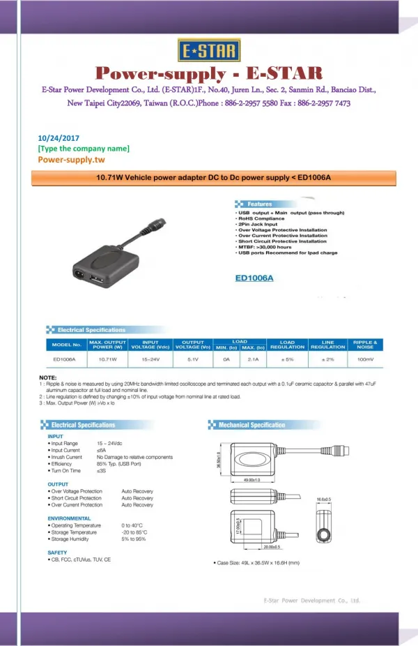
SMPS - Switch Mode Power Supply DC Power Supply
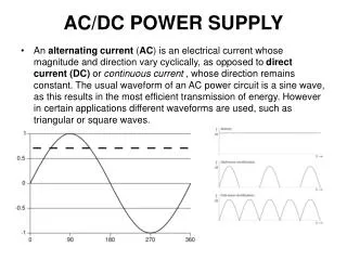
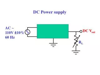
INTRODUCTION • Previous DC-DC converters (Buck, Boost, Buck-Boost) do not provide electrical isolation between input and output - these are non-isolated DC-DC converters • In most applications, isolation is required and this can be provided by transformers Controls One possible solution: To the LOAD AC, 50hz supply DC-DC Converters (non-isolated) PROBLEMS: Transformer operated at 50Hz frequency require large magnetic core – bulky, heavy and expensive ! SOLUTIONS: Use transformer at switching frequency – smaller core size Turns-ratio provides flexibility to the design Can provide multiple outputs
TRANSFORMER MODEL For SEE 4433 simplified model of transformer will be used to describe the circuit operation of SMPS I1 I2 ✔ Ideal model, + V1 + V2 ✔ Simplified model: no leakage and winding resistances Lm R1 Ll1 Ll2 R2 Detailed model: leakage inductances, winding resistances, magnetizing inductance, losses Rc Lm
FLY-BACK • Derived from Buck-Boost converter • Isolation provided by high frequency transformer
FLY-BACK Derivation of output voltage , Vo (ΔiL)closed + (ΔiL)open=0 Inductor volt-second balanced (Average inductor voltage = 0) OR
FLY-BACK Derivation of output voltage , Vo Switch CLOSED (ON) Switch OPEN (OFF)
FLY-BACK Derivation of output voltage , Vo Switch CLOSED (ON) Switch OPEN (OFF) (ΔiL)closed + (ΔiL)open=0 Inductor volt-second balanced (Average inductor voltage = 0)
FLY-BACK Waveforms for Fly-back Converter Closed Open
FLY-BACK Minimum Lm for continuous current Boundary condition when ILm,min= 0 It can be shown that:
FLY-BACK Output voltage ripple Derivation of output voltage ripple is similar to Buck-Boost converter It can be shown that the ration of the ripple to the output voltage is given by:
FULL-BRIDGE DC-DC CONVERTER The switches are switched in a pair: (SW1, SW2) and (SW3,SW4) (SW1, SW2) closed: (i) vp = Vs (ii) D1ON, D2OFF (iii) (SW3, SW4) closed: (i) vp = -Vs (ii) D1OFF, D2ON (iii)
FULL-BRIDGE DC-DC CONVERTER Derivation of output voltage , Vo Inductor volt-second balanced (Average inductor voltage = 0)
FULL-BRIDGE DC-DC CONVERTER Minimum Lx for continuous current Minimum Lx when ILx,min = 0
FULL-BRIDGE DC-DC CONVERTER Output voltage ripple From the figure
HALF-BRIDGE DC-DC CONVERTER Capacitors (C1 and C2) equally divide input voltage, theraforeVs/2 appear across primary when Sw1 closed and –Vs/2 when Sw2 closed. Hence