Download
1 / 58
580 likes | 741 Views
Module -2. DC Measurements. Objectives. 1. define voltage and give its unit of measurement; 2.identify the two different types of voltmeters; 3.connect a voltmeter in a circuit to measure voltage; 4.use a digital multimeter to measure voltage;

E N D
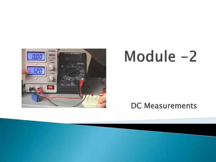
Module -2 DC Measurements
Objectives 1. define voltage and give its unit of measurement; 2.identify the two different types of voltmeters; 3.connect a voltmeter in a circuit to measure voltage; 4.use a digital multimeter to measure voltage; 5.define current and give its unit of measurement; 6.connect an ammeter in a circuit to measure current; 7.use a digital multimeter to measure current; 8.define resistance and give its unit of measurement; 9.determine the resistance value using the resistor color code chart; 10.use a digital multimeter to measure resistance Prepared by: Siti Hamimah Sheikh Ismail
Introduction • Where does the electricity in the television comes from? • Have you wondered how your laptop operates even when it is not plugged to the power socket? Prepared by: Siti Hamimah Sheikh Ismail
Two types of voltages Direct current (dc) Alternate current (ac) Prepared by: Siti Hamimah Sheikh Ismail
AC vs DC current path • http://www.youtube.com/watch?v=JZjMuIHoBeg Prepared by: Siti Hamimah Sheikh Ismail
Direct current (dc) • In DC, the flow of electric charge is only in one direction. • DC is produced by a battery and is used to power portable devices such as the cell phones, ipods, etc. Prepared by: Siti Hamimah Sheikh Ismail
DC current path • http://physics.weber.edu/amiri/director/DCRfiles/Electricity/batte11s.dcr Prepared by: Siti Hamimah Sheikh Ismail
AC: Alternating Current • In AC, the flow of electric charge periodically reverses direction. • http://www.science-animations.com/support-files/electricityweb.swf • AC is generated in a power plant and is delivered to the electric outlets in your home and buildings. • Washing machines, television, water heater etc. operate on ac. wall outlet/power socket Prepared by: Siti Hamimah Sheikh Ismail
When you do have devices that can work on batteries as well as when plugged into a regular electrical outlet (a laptop computer, for example), the circuits inside the device are usually designed to work on DC, and will convert the AC electricity into DC when it is plugged into an electric outlet. Prepared by: Siti Hamimah Sheikh Ismail
Video- Voltage • http://www.youtube.com/watch?v=elrbkYQyev0 Prepared by: Siti Hamimah Sheikh Ismail
Voltage Measurement • Voltage is the electric force that drives current around an electric circuit. • The unitof voltage is the volt, and is denoted by the symbol ‘V’. • Most cellsproduce a voltage of about 1.5V (dc), • and the voltage delivered through the power socket to houses and businesses in the UAE is 230V (ac). • On high-power transmission lines the voltage may be as high as 132kV (ac). Prepared by: Siti Hamimah Sheikh Ismail
132kV 230V Prepared by: Siti Hamimah Sheikh Ismail
Voltmeters • A voltmeter is used to measure voltage. There are two types of voltmeters as shown. Analog Voltmeter Digital Voltmeter Prepared by: Siti Hamimah Sheikh Ismail
The analog voltmeter measures voltage by deflecting a needle against a scale • A digital voltmeter displays the voltage value in digits. • Voltage may also be measured using a digital multimeter (DMM) • When voltage is measured, the difference of electrical force at two points is measured. Therefore, touch the two points with the probes to measure the difference. Prepared by: Siti Hamimah Sheikh Ismail
Measuring voltage • Step 1: Set the multimeter knob to read voltage (dc or ac) and select the range. • Step 2: Connect the two probes with proper polarity in parallel with the component/ device, across which the voltage is to be measured. • Step 3: Switch ON the meter and read the voltage. • Note: For unknown voltages, it is better to begin with the biggest range, and then reduce the range as this will protect the meter. Prepared by: Siti Hamimah Sheikh Ismail
symbol of a voltmeter Prepared by: Siti Hamimah Sheikh Ismail
Activity • http://www.wisc-online.com/Objects/ViewObject.aspx?ID=ENG802 • http://www.wisc-online.com/Objects/ViewObject.aspx?ID=AMT2204 Prepared by: Siti Hamimah Sheikh Ismail
Skill 1 Prepared by: Siti Hamimah Sheikh Ismail
Skill 1 To connect a voltmeter in a circuit to measure voltage Prepared by: Siti Hamimah Sheikh Ismail
Connect a voltmeter to measure the voltage across Bulb-A Prepared by: Siti Hamimah Sheikh Ismail
Lab Activity 1. measuring voltage Prepared by: Siti Hamimah Sheikh Ismail
Objective • To measure dc voltage and current using a multimeter Prepared by: Siti Hamimah Sheikh Ismail
Module 1 Part 2 Prepared by: Siti Hamimah Sheikh Ismail
Recap and refresh • Name the type of voltages for these two circuits. • Circuit 1Circuit 2 • http://www.folksemantic.com/visits/69063 • Construct a simple circuit and explain how we measure voltage across resistors. Prepared by: Siti Hamimah Sheikh Ismail
Objective • define current and give its unit of measurement; • connect an ammeter in a circuit to measure current; • use a digital multimeter to measure current; • define resistance and give its unit of measurement; • determine the resistance value using the resistor color code chart; • use a digital multimeter to measure resistance Prepared by: Siti Hamimah Sheikh Ismail
Current Measurement • Current is a measure of the flow of electrons in an electric circuit • Current is measured in amperes (A) and is denoted by the symbol ‘I’. • Small amount of current is measured in milliamperes (mA) and microamperes (µA). • A torch bulb uses 60mA or less. Prepared by: Siti Hamimah Sheikh Ismail
ammeter • The instrument that could be used to measure current is an ammeter. The ammeter symbol is given in fig • Current can also be measured with a multimeter • When current is measured, the meter has to be part of the circuit and therefore it must be placed in series with the component . Prepared by: Siti Hamimah Sheikh Ismail
measuring current: Follow the steps below to measure current • Set the multimeter knob to read current (dc or ac) and select the range. • Break the circuit and insert the multimeter probes across the break to complete the circuit. • Switch ON the meter and read the current. Prepared by: Siti Hamimah Sheikh Ismail
Measuring current • http://www.folksemantic.com/visits/73141 • Visit the website above and follow the step by step instructions Prepared by: Siti Hamimah Sheikh Ismail
Skill 2 Measure current Prepared by: Siti Hamimah Sheikh Ismail
To connect an ammeter in a circuit to measure current • Connect an ammeter in the circuit to measure the current through the Bulb-B. Redraw the circuit with the ammeter and use proper circuit symbols. Prepared by: Siti Hamimah Sheikh Ismail
Connect an ammeter in the circuit to measure the total current supplied by the voltage source V1 and the current through Light 1. Redraw the circuit, and use proper schematic symbols Prepared by: Siti Hamimah Sheikh Ismail
Lab Activity 1 Measuring current Prepared by: Siti Hamimah Sheikh Ismail
Module 1 Part 3 Prepared by: Siti Hamimah Sheikh Ismail
Objective • determine the resistance value using the resistor color code chart; • use a digital multimeter to measure resistance Prepared by: Siti Hamimah Sheikh Ismail
Resistance Measurement • Resistance is a measure of the opposition to the flow of current • It is measured in ohms (Ω) • and is denoted by the symbol ‘R’. http://mste.illinois.edu/users/Murphy/Resistance/default.html Prepared by: Siti Hamimah Sheikh Ismail
Ohm’s Law According to Ohm’s law, V = IR where R is the resistance in ohms, V is the voltage in volts and I is the current in amperes. Therefore, R=V/I, and so, in order to measure resistance, a meter measures both the current and the voltage. http://www.teachersdomain.org/resource/hew06.sci.phys.maf.ohmslaw/ Prepared by: Siti Hamimah Sheikh Ismail
Ohmmeter • The instrument used to measure resistance is called the ohmmeter. Its schematic symbol is • A multimeter can also be used to measure resistance. • The component must be removed from the circuit for accurate measurements. Prepared by: Siti Hamimah Sheikh Ismail
Resistance measurements Follow the steps below to measure resistance • Set the multimeter knob to read resistance (Ω) and select the range. • Remove the component to be measured from the circuit and connect it across the probes. • Switch ON the meter and read the resistance. Prepared by: Siti Hamimah Sheikh Ismail
Resistance color code • The value of resistance is determined by the formula: Color1 Color2 x 10Color3 • The gold and silver color bands indicate the value of tolerance which is a measure of variation from the true or actual value. • http://www.mrfizzix.com/resistor.html Prepared by: Siti Hamimah Sheikh Ismail
Activity – color code • http://www.wisc-online.com/Objects/ViewObject.aspx?ID=DCE1002 Prepared by: Siti Hamimah Sheikh Ismail
Example • Calculate the resistance of the resistor which has the following color code: R = Color1 Color2 x 10Color3 = 2 5 X 102 = 2500Ω = 2.5kΩ. Tolerance= + 5%. Therefore, R =2.5kΩ+ 5% Prepared by: Siti Hamimah Sheikh Ismail
Skill 3 Measuring resistance Prepared by: Siti Hamimah Sheikh Ismail
Skill 3. • To determine the resistance from its color code Find the resistance of the resistors with the following color code Prepared by: Siti Hamimah Sheikh Ismail
Lab Activity 2 Measuring resistance Prepared by: Siti Hamimah Sheikh Ismail
Lab Activity 1 • Objective:To measure dc voltage and current using a multimeter. • Procedure: Voltage Measurement 1.Find the voltages across different items listed in the table 5.2. 2.Set the multimeter to read dc voltage. 3.Select the appropriate range. 4.Connect the multimeter probes with proper polarity across each of the items listed in table 5.2. 5.Record the voltage readings for each. (Use the Feedback kit console power supply, for power supply voltage measurements.) • Complete table 5.2 Prepared by: Siti Hamimah Sheikh Ismail
Observation: Prepared by: Siti Hamimah Sheikh Ismail
Current Measurement • Find the current through the resistors listed in table • Construct the simple circuit shown below in. Use 330 Ω resistor value. Prepared by: Siti Hamimah Sheikh Ismail
Procedure: currentMeasurement • Set multimeter-A to read voltage and multimeter-B to read current. • Connect the multimeter-A to read voltage to the power supply. • Make sure that the variable dc control knob is fully counter clockwise, and then switch on the power supply. • Increase the applied voltage to 4 V • Read the current displayed in multimeter-B and ecord the current reading in table 5.3 • Increase the voltage to 10V and record the current. • Replace the 330Ω resistor with 1000 Ω and repeat the above steps Prepared by: Siti Hamimah Sheikh Ismail
Observation: Prepared by: Siti Hamimah Sheikh Ismail