Download
1 / 8
80 likes | 167 Views
METHOD FOR DESIGN & ANALYSIS OF ORIFICES FOR USE IN REACTOR COOLANT PUMP TEST LOOPS. Summary Presentation JEFFREY STACK Masters Project December 2011. Outline. Introduction Problem Description Methodology Expected Results Sizing of the Orifices. Introduction.

E N D
METHOD FOR DESIGN & ANALYSIS OF ORIFICES FOR USE IN REACTOR COOLANT PUMP TEST LOOPS Summary Presentation JEFFREY STACK Masters Project December 2011 December 2011
Outline • Introduction • Problem Description • Methodology • Expected Results • Sizing of the Orifices December 2011
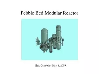
Introduction • Reactor Coolant Pumps (RCPs) • Function • Testing Requirements • Characteristics that are tested • Challenges to Testing • Conditions • Very specific requirements • Net Positive Suction Head • Very low pump suction pressures December 2011
Problem Description • Harsh Testing Conditions for all Components • In particular, NPSH testing conditions • Cavitation in Restriction Orifice • Large Δp & Large reduction in flow area • Task – Dual Orifice System Design • To minimize flow area reduction • Hydraulic Design • Includes sizing and any flow specific geometries • Structural Design • Includes static and dynamic analysis of the orifices December 2011
Methodology • Size Orifice & Determine Detailed Geometry • Using Idelchick’s “Handbook of Hydraulic Resistance” • Create 3D Model • Using ANSYS Workbench • Perform Static Structural Analysis • Using ANSYS Workbench by applying the Δp on the front face of the orifice • Perform Dynamic Structural Analysis • Using ANSYS Workbench to determine orifice natural frequencies December 2011
Expected Results • Two Orifice System Minimizing Cavitation • Orifice System to be Capable of Testing at 2 Flow Points by Removal of One Orifice • Structurally Sound for all Testing Conditions • Natural Frequency not to Overlap Typical Pump Blade Passing Frequencies December 2011
Sizing of Orifice 1 • Using the required Δp of 663.5kPa to achieve the high flow point, Orifice 1 is sized using the following correlation from Idelchick • Where Fo is the flow area of the orifice which is solved for • The inner diameter of Orifice 1 is determined to be 0.551m December 2011
Sizing of Orifice 2 • To determine the required Δp for Orifice 2, a new Δp of Orifice 1 is calculated for the low flow point • This new Orifice 1 Δp is subtracted from the total (Orifice 1 & 2 combined) Δp of 1143.0kPa, which is required to achieve the low flow point • The Orifice 2 Δp is determined to be 890.4kPa • Using the correlation on the previous slide, the Orifice 2 inner diameter is determined to be 0.448m December 2011