Download
1 / 45
460 likes | 493 Views
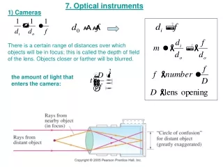
Optical Instruments II. Instruments for Imaging the Retina. 1. Fundus Camera. Fundus camera optics are very similar to those of the indirect ophthalmoscope. principle of indirect ophthalmoscope. same principle for fundus camera. GTT 04. GTT 04. Practical Retinal Illumination System.

E N D
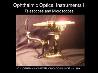
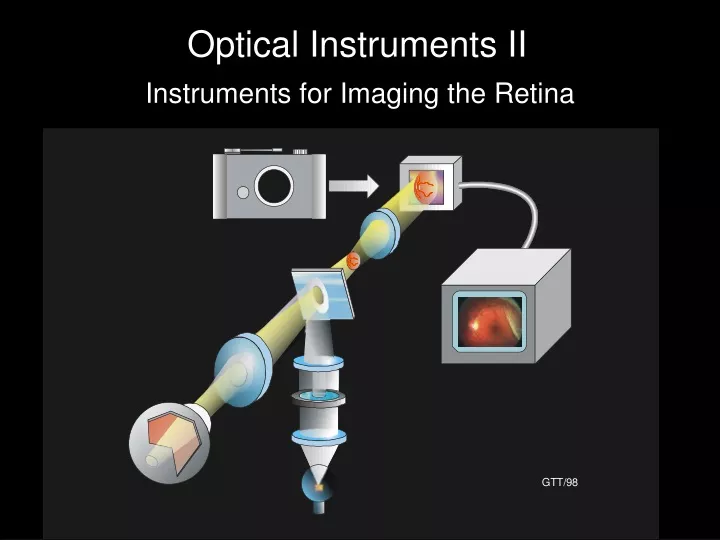
Optical Instruments II Instruments for Imaging the Retina
1. Fundus Camera Fundus camera optics are very similar to those of the indirect ophthalmoscope.
principle of indirect ophthalmoscope same principle for fundus camera GTT 04
Fundus camera camera or CCD
2. Scanning Laser Ophthalmoscope (SLO) Uses much lower light levels than fundus camera – continuous viewing. Many wavelengths including IR—no mydriasis
Confocal Principle Red cell in thick sample imaged by lens Pinhole in image plane passes all light from blue cell Blue cell, nearer to surface, imaged at different point Pinhole blocks most of light from red cell Based on Webb, RH, Rep Prog Phys 59:427
SLO Raster Scan Slower vertical scan (17 mS) Video rate raster pattern Fast (35 mS) horizontal line scan
video monitor laser photo- detector AOM pinhole laser-beam raster on retina vertical scan—60 Hz rotating faceted mirror—40,000 rpm
Video source (computer, camera) laser Acousto-Optic Modulator video monitor laser-beam raster on retina
SLO more light efficient than fundus camera SLO FUNDUS CAMERA exit pupil exit pupil iris pupil illumination illumination
SLO with Adaptive Optics (AO) Corrects laser beam aberrations caused by eye’s optics. Results in very high resolution images of retina.
AO SLO beamsplitting mirror micromirror array laser X – Y scan aberration signals Hartmann-Shack wavefront sensor
Human retina AO SLO AO turned on A. Roorda UC Berkley
AO SLO optical sectioning (images in depth) A. Roorda UC Berkley
Laser Beam Coherence Laser coherence length
Michelson Interferometer reference arm sample arm
low coherence length long coherence length
video monitor electronics Michelson Interferometer Optical Coherence Tomography
reference arm sample arm video monitor sample electronics
IN MICHELSON INTERFEROMETER Fringes form when reference mirror path length matches path length of a reflective piece in the tissue in the sample arm. Fringes only form when the path difference is within the coherence length of the light source.
A SCAN B SCAN video monitor electronics
OCT using fiber optics electronics sample reference SLD photodetector
Axial (‘A’) scan comes from mirror movement in time. Resolution in both directions about 10 mm. About 750 A scans/sec 1 – 2 sec for one complete image Eye movements a problem Time Domain OCT’s
Fourier Domain OCT (FDOCT) Called this because raw output of the OCT is the Fourier transform of the depth reflectance signal. Reference mirror stationary Reflectance of tissue at each depth recorded simultaneously Two types: Swept Source (SSOCT) & Spectral Domain SDOCT)
Swept-Source FDOCT fixed ref mirror swept l laser electronics inverse Fourier transform I 1/l (wavenumber) Distance (mm)
TDOCT FDOCT ~ m m 10 m < 3 m Axial & lateral resolution 750 16,000 A-scans/sec 1 – 2 sec 0.03 sec Image formation time (512 A scans) FDOCT provides improved resolution and reduced image formation times compared to TDOCT
1,000 A scans. 17 images/sec Volumetric 3D image (5.7 sec) Fundus image from 3D data Bioptigen Inc.