Download
1 / 21
210 likes | 217 Views
LCLS Photon Systems Overview. John Arthur SLAC. New LCLS Organization Collects all X-Ray Activities into Photon Beam Systems. LCLS Photon Systems. Includes LCLS x-ray and laser groups X-ray Transport, Optics and Diagnostics (XTOD) managed by LLNL ( Richard Bionta )

E N D
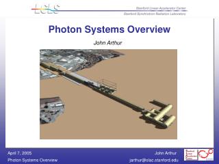
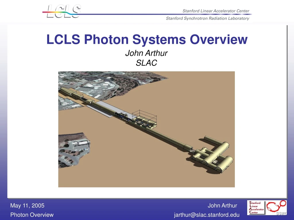
LCLS Photon Systems Overview John Arthur SLAC
New LCLS Organization Collects all X-Ray Activities into Photon Beam Systems
LCLS Photon Systems Includes LCLS x-ray and laser groups • X-ray Transport, Optics and Diagnostics (XTOD) • managed by LLNL (Richard Bionta) • X-ray Endstation Systems (XES) • managed by SLAC (Stefan Moeller) • LCLS Laser Systems • managed by SLAC (Bill White)
XTOD Scope • Transport the x-ray beam, in vacuum, to all the experimental stations • Condition the x-ray beam, with attenuators and apertures • Analyze the x-ray beam, with sophisticated diagnostics
XES Scope The X-Ray Endstation Systems group provides the infrastructure required for experimenters to make best scientific use of the LCLS radiation safely
Instrument MIE and XES • A ~$50M MIE project has been proposed • Will build 4 x-ray instruments for LCLS • Instrumentation needs are becoming much more clear • XES has decided not to build generic instrumentation but rather, • LCLS will dedicate all project effort for experimental instrumentation to one area of science: Soft X-ray Atomic Physics (AMO)
Instrument MIE and XES Detectors • LCLS experiments need new detector technology • Dual development strategy for fast 2-d detectors • Several technologies look promising, no clear leader • LCLS will pursue one strategy • MIE will try a different technology • Both prototypes should be ready by 2009
LCLS Detector Development Program • Silicon Pixel Array Detector technology • Subcontracted to Gruner group at Cornell • About $3.5M total over 4 years • MOU in signing stage • Detector scientist to be hired soon • Periodic review by LCLS Detector Advisory Committee • Detailed specs being developed to match needs of single-particle imaging experiment
Recent Developments affecting all X-ray Systems (and Conv. Facilities) • Suggested Plan for Offset Mirrors in Front End • Suggested Redesign of Far Experimental Hall These ideas are in the development stage, not yet official But they look very promising Have been endorsed by SAC
High Energy background problem • Unfiltered LCLS beam contains significant background from spontaneous harmonics (Ec ~ 150 keV) and from Bremsstrahlung from scattered electrons (GeV) • Much of this background lies directly on axis, and it is time-coincident with the FEL pulse • This is a nuisance for radiological shielding, and a huge problem for data taking
Solution: Offset mirrors in the FEE Upstream of all LCLS experiments FEL radiation reflected (>95%) SiC 1.5mrad SiC 1.5mrad 24mm offset Background from high harmonics and Bremsstrahlung not reflected
Two mirror pairs, one pair inserted at a time SiC gives cutoff at 24 keV Be gives cutoff at 2 keV SiC 1.5mrad Be 13mrad SiC 1.5mrad 24mm offset 8.0m
Reflectivity vs energy for a flat SiC mirror at 1.5 mrad incidence angle R > 95% for E < 24 keV R < 10% for E > 28 keV From Berkeley CXRO calculator: <http://www.cxro.lbl.gov/optical_constants/mirror2.html>
Proposed new layout of FEE 7 ft Fe 4 ft Fe 3 ft concrete Mirrors GAS ATTEN COLLIM STOP STOP SOLID ATTEN ~30m
Advantages of Offset Mirrors • Keep high-energy radiation out of experiments • Eliminate troublesome background • Note: nearly all synchrotron beamlines use some offset • Keep high-energy radiation farther away from experimenters • Reduce shielding requirements, make hutches more easily accessible
Far Experimental Hall Redesign • Response to concerns of experimenters and LCLS Technical Advisory Committee • Now in Title-1 planning stage
Problems with FEH Office and shop space (Vac., Mech.,Electr.) Experimental hutches (7x8m) TOO SMALL FEL beams
New FEH design Entrance 14ft tunnel Fire door Fire door 15x25ft control cabin 46ft tunnel Sliding hutch door passage below beam pipe 6ft 10ft 28x33ft hutch 10ft 29x33ft hutch 36x33ft hutch 10ft 30ft transition Toilets 20ft tunnel Future tunnel to other stations 212ft
Advantages of new design Wider main tunnel Reduced corridor space More space for x-ray optics Large hutches Slightly higher cost
Summary • Photon sections of LCLS are just starting up • Major staff increase • Experimental needs coming into focus • Design changes • Offset mirrors • FEH redesign