Download
1 / 34
340 likes | 347 Views
LCLS Radiological Considerations. Alberto Fasso, Stan Mao, Noriaki Nakao, Sayed Rokni, Heinz Vincke Radiation Protection Department Stanford Linear Accelerator Center October 18, 2005. Components along the LCLS. LCLS Injector LINAC BSY/LCLS Beam Transport Hall (BTH)

E N D
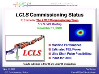
LCLS Radiological Considerations Alberto Fasso, Stan Mao, Noriaki Nakao, Sayed Rokni, Heinz Vincke Radiation Protection Department Stanford Linear Accelerator Center October 18, 2005
Components along the LCLS LCLS Injector LINAC BSY/LCLS Beam Transport Hall (BTH) Undulator Hall (UH) Electron Dump/Dump line Front End Enclosure (FEE) Near Experimental Hall (NEH) X-ray Transport Optics Diagnostic (XTOD) Far Experimental Hall (FEH)
LCLS beam parameters Injector: e- 135 MeV, 16 W LINAC: e- 15 GeV, 5 kW MCB: e- 15 GeV, 150 kW X-ray: photon 140 keV (Ec), 2.7 W FEL: photon 8.2 keV (1st Harmonic), 0.3 W
LCLS Injector shielding wall Hazards: Radiation generated during PEP-II/LINAC operation. Shielding allows access to the vault during PEP-II and LINAC operation Status The shielding wall was approved by the Radiation Safety Committee on March 28, 2003 Shielding was built in August/September 2004. The penetrations through the shielding wall will be installed in October downtime.
LCLS Injector Hazards: Radiation generated during the LCLS Injector operation from beam losses on Faraday Cups, OTRs, dump may reach the laser room above through penetrations Status Preliminary calculations were completed BCS, PPS to be designed PPS plans to use PLC
Radiation Levels (mrem/hr) 6.2 MeV, 0.744 W beam on Faraday cup FLUKA Calculations
LINAC Hazards: Sources: Beam loss in collimators located in LCLS Bunch compressor (BC) 1 and 2, temporary dump near BC1 Radiation in the linac klystron gallery through penetrations Status Radiation in the linac klystron gallery to be calculated
BSY/LCLS Hazard: Sources: 5 kW of beam loss in single beam dump Muons, neutrons and photons penetrate the BTH shielding walls Status Preliminary calculations were completed, 9’ of iron is required Calculations to be revised Issues under study include: ray-trace studies for energy chicane
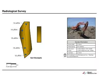
Beam Transport Hall Hazards: Sources: 5 W loss at any point, 417 W on tune up dump Status Shielding design for BTH wall and roof – completed Details are being worked out with JACOBS, LCLS Issues under study include: detailed design of entrance mazes, cable penetrations, ventilation ducts Other issues Remanent radiation from dump Soil/water activation from dump
BTH UNDULATOR HALL ELECTRON BEAM DUMP & FEE NEAR EXPERIMENTAL HALL AND CENTRAL LABS & OFFICE X-RAY TRANSPORT & DIAGNOSTICS TUNNEL FAR EXPERIMENTAL HALL Beam Transport Hall
Undulator Hall Hazard: 5 W loss at any point Radiation in the service buildings through penetrations Status Radiation analysis through cable penetrations was completed Radiation through ventilation ducts to be calculated
Electron Dump/Dumpline Hazards: Sources: 30 W loss at any point, 5 kW on the dump Status Shielding design for Dump – completed Maze to Dumpline - completed Details are being worked out with JACOBS, LCLS Muon shielding calculations completed, 7’ of iron, 4’ of concrete and a muon spoiler is required Calculations to be revised based on new lay-out E- dump system to be studied (DC magnets are used) Other issues Remanent radiation from dump – completed Soil/water activation from dump– completed
Residual Dose Rate & Activity around Beam Dump by MARS15 14.1GeV 5kW electron beam Below 0.01 mSv/h at top concrete Residual Dose Rate [mSv/h] (30-day operation 1-day cooling)
Front End Enclosure Hazards: High energy bremsstrahlung – 800 mW Spontaneous X-ray – 2.7 W Free Electron Laser – 0.3 W Status Maze to FEE - completed Details are being worked out with JACOBS, LCLS The high energy bremsstrahlung and spontaneous synchrotron radiation produced in the undulator have to be minimized to conduct FEL experiments successfully
Effective dose – C2 and C3 out2 kW on Optical Transition Radiator (OTR) 385 mW ± 0.07 % through C1 – 90 mW ± 1.7 % through C4 Total effective dose rate in mrem/h (100 mrem/h≡1 mSv/h)
Effective dose rate all collimators aligned - 2 kW on OTR 385 mW ± 0.07 % through C1 – 0.17 mW ± 18 % through C4 C2 out: 385 mW ± 0.07 % through C1 – 17 mW ± 2 % through C4 Total effective dose rate in mrem/h (100 mrem/h≡1 mSv/h)
Near Experimental Hall Hazards: High energy bremsstrahlung – 17 µW Spontaneous X-ray reflected by one mirror is scattered by an object inside the hutch Free Electron Laser reflected by one mirror is scattered by an object inside the hutch Status Shielding design - completed Details are being worked out with JACOBS, LCLS Issues under study include: detailed design of cable penetrations, laser penetrations, ventilation ducts and doors
Dose rate at experimental hutch forward shielding • 17 mW through C4 • Cu cube: • L = 2.54 cm • Required: • 2 ft concrete wall + local iron shielding
Dose rate at experimental hutch side shielding • 17 mW through C4 • Cu cylinder: • r = 2.54 cm, • L = 15 cm
X-ray Transport Optics Diagnostic (XTOD) Hazards: Spontaneous X-ray reflected by two mirrors is scattered by an object Free Electron Laser reflected by two mirrors is scattered by an object Status No access during operation Issues under study include: detailed design of cable penetrations, ventilation ducts
Far Experimental Hall Hazards: Spontaneous X-ray reflected by two mirrors is scattered by an object inside the hutch Free Electron Laser reflected by two mirrors is scattered by an object inside the hutch Status Preliminary shielding design was performed Hutch lay-out is not finalized Issues under study include: hutch shielding, detailed design of cable penetrations, laser penetrations, ventilation ducts and doors
Beam Containment System BCS requirements for e- beam line (devices, locations and trip levels) need to be defined by RP/LCLS BCS for FEL (Burn-through issue) to be studied Trip mechanism to be designed by LCLS
Personnel Protection System PPS zones and access modes to be determined by LCLS PLC system and specification to be approved Hutch Protection System (HPS) to be designed by LCLS BSOIC specification and locations to be provided by RP Burn-through monitor specification and locations to be provided by RP
Summary Radiation sources for various sections of the LCLS have been identified Title II 30% review was completed Title II 60% review starts on October 28, 2005 Penetrations, ventilation ducts, doors and FEH hutches are not finalized Remaining issues, which are not discussed in this talk, are listed
Other Radiological Considerations • Other radiological safety issues considered are: • Dumpline, FEE and NEH PPS stopper design (damage and safety issue) • Shielding design of High-energy and low-energy hutches for Near Experimental Hall using four-collimator system • Accident and mis-steering doses • Inventory for possible activated components • Skyshine dose to public • Air activation • Dismantling FFTB • Using radioactive iron blocks as LCLS shielding • Removing the earth from Research Area Road near ESA Dump D400 • Radiation damage to undulator and magnets