Download
1 / 35
470 likes | 820 Views
Fin-tube Condenser and Evaporator With Delta Winglet in Window A/C. P M V Subbarao Associate Professor Mechanical Engineering Department IIT Delhi. Simple Rankine Cycle. 3. 2. 1. 4. Reversed Rankine Cycle. 3. 2. 1. 4. Ideal Vapor Compression Refrigeration Cycle. 2. 3. 4. 1.

E N D
Fin-tube Condenser and Evaporator With Delta Winglet in Window A/C. P M V Subbarao Associate Professor Mechanical Engineering Department IIT Delhi
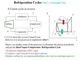
Simple Rankine Cycle 3 2 1 4
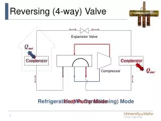
Reversed Rankine Cycle 3 2 1 4
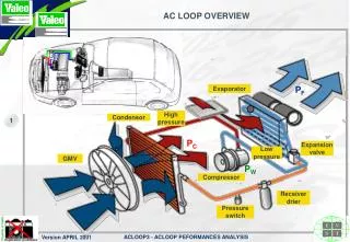
Fin & Tube HXs: Condenser & Evaporator • Refrigerant R22, Condenser heat rejection = 2700W
Design of Fin Tube arrangements of the heat exchanger
Fluid Properties • Inlet temperature of air, Tai= 350C • Outlet temperature of air, Tao= 250C • The properties of air were calculated at the bulk mean temperature, 300C.
The properties of refrigerants were calculated at the evaporation temperature,at 7.20C.
Airside Analysis • The frontal area of the evaporator, Afr =L1*L3 • The rate of heat transfer in the evaporator =2000W • Temperature drop of air across the evaporator, • DT =Tai-Tao • Mass flow rate of the air was calculated as, • Mass velocity of air based on minimum free flow area was calculated as
For the staggered tube arrangement, the minimum free flow area, Amin was calculated by using the unit cell analysis and the results are:
Reynolds number based on Gair is calculated by • Where hydraulic diameter Dh, is given by • The total heat transfer area, A was associated with the exposed tubes and fins. • The primary and secondary heat transfer surface areas for staggered finned tubes are given by
Airside heat transfer coefficient ha is calculated, using the correlations by Turaga et al. 1988 for heat transfer and pressure drop factor for direct expansion evaporator
Reynolds number, Rer is calculated as Tube side analysis • Prandtl number, Prr is calculated as • Heat transfer coefficient for the refrigerant boiling inside the tube is calculated using Bo Pierre’s correlation, that is valid for complete evaporation of the refrigerant and 60C of superheat at the exit of the evaporator.
Calculation for the number of rows in the evaporator • The overall heat transfer coefficient for the fin-tube heat exchanger was calculated as
Inline Arrangement AUTOCAD drawing of the condener
Staggered Arrangement AUTOCAD drawing of the condenser
The most important part of the set-up ‘Condenser & Evaporator were fabricated in collaboration with Spirotech Heat Exchangers Pvt. Ltd. Bhiwadi. • The design of the condenser in AUTOCAD was provided to the coil manufacturer and the fabrication was personally supervised. • For punching the winglets a special tool was fabricated which had to be operated manually. The tool punched out winglets in front of one tube at at time. • Condenser Specifications: • Fin spacing = 3.9 mm • Fin thickness = 0.15 mm • Frontal area = 0.3m x 0.3m • Number of rows = 6 • 5. As mentioned earlier, two identical condenser with the only difference of winglets were fabricated
Various components procured from different Industry /Supplier Major Components
Observations of test performed • Condenser air outlet temperature varies substantially as compared to other variables. Experimental Observations
97.1 97 51.2 51 51 48 36.5 37 Refrigerant Refrigerant Air Air Temperatures in condenser with winglet Temperatures in condenser without winglet LMTD = 10.57 LMTD = 19.027 • For accounting the difference of LMTD (currently assuming that the heat transfers do not change too much) the product UA of condenser with winglet should be proportionately higher. • The area of heat transfer is not differing in both the condensers. So, in UA only U of condenser with winglet would be higher. Discussion of Results