Download
1 / 35
350 likes | 468 Views
A DAQ Architecture for the Agata experiment. Gaetano Maron INFN – Laboratori Nazionali di Legnaro. Outline. On-line Computing Requirements Event Builder Technologies for the On-line System Run Control and slow Control Agata Demonstrator 2003-2007 Off-line Infrastructure Conclusions.

E N D
A DAQ Architecture for the Agata experiment Gaetano Maron INFN – Laboratori Nazionali di Legnaro
Outline • On-line Computing Requirements • Event Builder • Technologies for the On-line System • Run Control and slow Control • Agata Demonstrator 2003-2007 • Off-line Infrastructure • Conclusions
Agata Global On-line Computing Requirements Front-end electronic and pre-processing 1000 Gbps (4 Gbps x 200) Pulse Shape Analysis 1.5 x 10⁶ SI95(?) (present algorithm) Max 10 Gbps (50 Mbps x 200) Event Builder 5 x 10³ SI95 10 Gbps Tracking 3 x 10⁵ SI95 (no GLT) 3 x 10⁴ SI95 (GLT @ 30 kHz) 1 Gbps SI95 = SpecInt 95 1 SI95 = 10 Cern Unit = 40 MIPS GLT = Global Level Trigger Storage
Pulse Shape Analysis Farm DSP DSP Mux DSP FADC PC DSP FADC FPGA PREAM Detector i=1-200 PSA Farm 50 Mbps x 200 1 Gbps x 200 1.5 MSI95 (now)
Event Building: simple case R200 R1 R2 PSA Farms R3 Clock T01 T02 T04 T01 T02 T01 T02 T03 T04 T01 T03 T01 T03 Time Slot 1 T05 T06 T07 T07 T08 T07 T05 T06 T09 T12 T05 T06 T07 T08 T09 T12 T09 T10 T12 Time Slot 2 T09 T09 T10 T11 T12 Time Slot 3 Builder Network (10 Gbps) BU1 BU2 BUn Builder Units Where n could range (now) from 10 to 15 according to the efficiency of the event builder algorithm and to the communication protocol used In the final configuration (after 2005) we could image To have a single 10 Gbps output link and a single BU
Time Slot Assignment Ev # Ev # Ev # Ev # Ev # Ev # Ev # Ev # Ev # Ev # Ev # Ev # TTC assigns EV # (time stamp) Detector Slice Ev # Det i Ev # Ev # MUX buffers events according to a given rule and then define the Time Slot MUX assigns a buffer # to this collection of events MUX Buf # Ev # Ev # All this is synchronous for all the detectors Event Merging in the EB Farm is then feasible Ev # MUX distributes the buffers to PSA farm According to their buffer # EB # Buf # PSA farm shrink down the incoming buffers, A further buffering is then needed PSA assigns a EB (Event Builder) # to the new buffers PSA distributes the buffer to Event Builder farm According to such number. Buf # Buf # PSA FARM Slice 200 Slice 2 Slice 1 EB FARM
Agata Event Builder: some more requirements R200 R1 R2 Readout Farms R3 Clck T01 T02 T04 T01 T02 T01 T02 T03 T04 T01 T03 T01 T03 Time Slot 1 T05 T06 T07 T07 T08 T07 T05 T06 T09 T12 T05 T06 T07 T08 T09 T12 T09 T10 T12 Time Slot 2 T09 T09 T10 T11 T12 Time Slot 3 Builder Network (10 Gbps) BU1 BU2 BU3 Builder Units - delayed coincidence can span more time slots. - fragments of the same events are in different BUs.
HPCC for Event Builder Builder Network High Performance Computing and Communication (HPCC) System - High speed links (> 2 Gbps) - low latency switch - fast inter processor comm - low latency message passing
Agata on-line system F200 F1 F2 F3 Front-End 1000 Gbps R200 R1 R2 R3 PSA Farm 10 Gbps Event Builder Builder Network B20 B1 B2 HPCC builder 10 Gbps Tracking Farm 1 Gbps ds1 ds4 ds2 ds3 Data Servers 1 Gbps Storage (1000 TB) 100 Mbps > 1 Gbps
Technologies for Agata On-line System • Networking Trends • Event Builder • CPU Trends • Building blocks for the Agata Farms • Storage Systems
Networking Trends - I Infiniband 10 GbEth 256 Gbps Myrinet 192 Gbps • Local networking is not an issue. Already now Ethernet fits the future needs of the NP experiments • link speed max 1 Gbps • switch aggregate bdw O(100) Gbps • O(100) Gbit ports per switch • O(1000) FastEthernet per switch • If HCCP is requested (e.g. Agata builder farm) options are Myrinet, Infiniband = 4 x Myrinet GigaEthernet 128 Gbps Aggregate bandwidth within a single switch 64 Gbps 2000 2001 2002 2003 250 MB/s Myrinet one way latency Myrinet throughput 10 msec latency time
Networking Trends II: Infiniband 110 mm Storage Target Channel based message passing TCA Internet Intranet MemCntlr CPU 1 HCA Link Link Link Link Switch MemCntlr CPU HCA 2 Link Link Link TCA N/W Target MemCntlr CPU HCA 3 Link Link 1000’s node per subnet Same network to transport low latency ipc, storage I/O and network I/O Link Link xCA Link speed 1x 2.5 Gbps 4x 10.0 Gbps . 12x 30 Gbps MemCntlr Router CPU HCA n New server form factor about 300-400 box per rack 222 mm 1 x Link 4 x Link 12 x Link
Raw GbEth EVB CMS
GbEth full Standard TCP/IP CMS CPU Load 100 %
TCP/IP CPU Off-loading - iSCSI • Internet SCSI (iSCSI) is a standard protocol for encapsulating SCSI command into TCP/IP packets and enabling I/O block data transport over IP networks • iSCSI adapters combines NIC and HBA functions. • take the data in block form • handle the segmentation and processing with TCP/IP processing engine • send IP packets across the IP network Storage HBA FC Storage iSCSI Adapter Network Interface Card Application Layer File Block Block IP Server FC Server IP Server I 80200 Processor Block Block Driver Layer IP Packets Link Layer Intel GE 1000 T IP Storage Adapter IP Packets IP Packets FC Packets on Ethernet on Ethernet
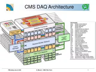
Comments on the Agata Event Builder • Agata Event Builder is not an issue (also now). CMS experiment has already shown the ability to work with an order of magnitudine better that the Agata requirements • Agata could work, also in the prototype, fully on standard TCP/IP • Agata could require an hpcc based Event Builder. Technologies already exist for that, but never applied to event builder problems. Should not be a big issue • Myrinet (now) • Infiniband (soon)
Processors and Storage trends 80 SI95 Now 250 GB Now Year 2007 1 disk = 1 TByte 2007 CPU = 250 SI95 2010 CPU = 700 SI95
Building Blocks for the Agata Farms 1 U CPU Box with 2 processors 40 Boxes x Rack Configurations Farms Type
Blade Based Farms 1 Blade Box with 2 processors 14 Boxes x crate (7 U) 6 Blade crates x rack = 108 Boxes Power = 16 KW x Rack Configurations backplane 30 Gbps backplane Farms Type SW2 SW1 2 x 4 x 1 Gbps uplinks
On-line Storage • On-line Storage needs • 1-2 weeks experiments • Max 100 TByte / experiment (no GBT) • Max 1000 TByte/year • 2010 1 disk = 4 Tbyte • Storage Agata System: 250 disks (+ 250 for mirroring) • Archiving • O (1000) TB per year can not be handled as normal flat files • Not only physics data stored • run conditions • Calibration • Correlation between physics data, calibration and run condition are important for off-line analysis • Data Base technology already plays an important role in physics data archiving (Babar, LHC experiments, etc.). Agata can exploit their experience and development
Storage Technologies Trends Application Servers Data Servers GEth/iSCSI SAN enabled disk array Infiniband gateway • Commodity Storage Area Network share all the • farms nodes. Technololgies interested for us are: • iSCSI over Giga (or 10 Giga) Ethernet • Infiniband • Full integration between the SAN and the farm is • realized if a Cluster File System is used. • Example of Cluster File System are: • LUSTRE (www.lustre.org) • STORAGE TANK (IBM)
Example of a iSCSI SAN available today Application Servers GEth/iSCSI Data Servers LSI logic iMegaRAID 1 = ~ 5 Tbyte x controller SATA 2 x GE 16 • Host adapters: • Intel GE 1000 T • Adaptec ASA-7211 • LSI 5201 • ecc. iSCSI Controller RAID – SATA Controller SATA = Serial ATA
Data Archiving Internet Intranet Data Servers Input Load balancing switch Low latency Interconnection (e.g. HPCC) Shared Data Caching (Oracle) Storage Area Network Scalability
Run Control and Slow control Front-end electronic and pre-processing Pulse Shape Analysis Slow Control Run Control and Monitor System Event Builder Tracking Storage
Run Control and Slow Control Technological Trends • Virtual Counting Room • Web based technologies • SOAP • Web Services and Grid Services (Open Grid Service Architecture) • Data Base • Demonstrators in operation at CMS test beams facilities
RCMS present demonstrators Java MySQL Java TomCat Containers Or Grid Services SOAP
Slow Control Trends • Ethernet every where • Agata could be fully controlled by Ethernet connections, including the front end electronics • This lead to have an homogeneous network avoiding the use of bridges between busses, software drivers to peform the bridging, etc. • Embedded web server and embedded java virtual machines on the electronics • Embedded Java should guarantee an homogeneous development environment, portability, etc. Tini system Xilink Virtex II Pro
Agata Demonstrator (2003-2007) F15 F1 F2 F3 Front-End P15 Blade Center P1 P2 P3 PSA Farm 15 x 2 Eth Switch Event Builder Builder Network 2 Dual processor Servers + Myrinet B1 B2 HPCC builder T1 T2 Tracking Farm Blade Center Storage Area network = iSCSI SAN Data Servers iSCSI Disk Array + SATA disks 8 + 8 TByte 16 16 1 1 1 Gbps 100 Mbps
Off-line Infrastructure > = 10 Gbps links Data Production Center: - on-line system - online storage (1000 TByte) - central archive ? • Exploit the LHC off-line infrastructure based on Regional Computing centers • Regional Computing facilities (e.g. Country bounded) are linked to the data center via 10 Gbps links. • All the computing facilities are based on PC farms • a typical experiment take about 1 day to copy the entire data set • no tape copy Regional Computing Facilities: - computing power for own analysis - on-line storage for 1-2 experiments - local archive
World Wide Farming: the GRID • GRID is an emerging model of large distributed computing. Main aims are: • Transparent access to multi-petabyte distributed data bases • Easy to plug in • Hidden complexity of the infrastructure • GRID tools can help significantly the computing of the experiments promoting the integration between data centers and the regional computing facilities • GRID technology fits the Agata experiment off-line requests HEP focused GRID initiatives - DataGrid (UE) - GriPhyN (USA) - PPDG (USA)
Summary • Fully adoption of digital electronics • increased on-line computing power needed to perform pulse shape analysis • Digital Signal Processors (DSP) embedded in the front-end electronics • Commodity components like PCs and networking devices • Trigger less systems (dead time free) • time stamp techniques are used to have dead time free systems • on-line computing power is needed to correlate data by applying prompt or delayed coincidence (event building) • On-line analysis • tracking systems needs O(105 ) SI95 • Storage • O(100) MB/s on the storage devices • Use of data bases for archiving. Advanced parallel server needed to follow the rate • Off-line analysis using GRID techniques • data storage O(1000) TB per year • international collaborations • data distributions • regional computing centers • GRID architecture
Conclusions • No fundamental technological issues for the final Agata on-line system: • The experiment requirements and the present understanding of the PSA algorithm fit with a final (2010) moderate size ( O(1000) machines) on-line system. Only a 3 times improvement in the PSA calculations lead to a system much more manageable (3 racks). • Both network and event builder issues already fit with the today available technologies. • Storage requirements (1000 TByte) fit with the evolution of the storage technologies. • On-line storage staging, high bandwidth network data transfer and GRID technologies allow data distribution over WAN ; tape only for backup. • Demonstrator • Same architecture of the final system, only scaled down to the foreseen number of detector.