Download
1 / 41
410 likes | 415 Views
Final Exam and End Material Test Friday, May 12, 10:00-12:00. Test rooms: Instructor Sections Room Dr. Hale F, H 104 Physics Dr. Kurter B, N 125 BCH Dr. Madison K, M B-10 Bertelsmeyer Dr. Parris J St. Pats Ballroom Dr. Parris L 112 Bertelsmeyer

E N D
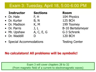
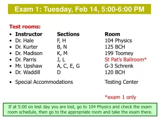
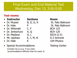
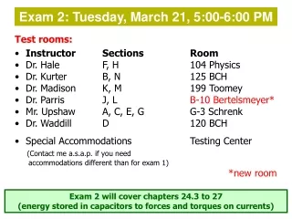
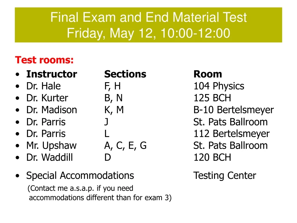
Final Exam and End Material Test Friday, May 12, 10:00-12:00 Test rooms: • Instructor Sections Room • Dr. Hale F, H 104 Physics • Dr. Kurter B, N 125 BCH • Dr. Madison K, M B-10 Bertelsmeyer • Dr. Parris JSt. Pats Ballroom • Dr. Parris L112 Bertelsmeyer • Mr. Upshaw A, C, E, G St. Pats Ballroom • Dr. Waddill D 120 BCH • Special Accommodations Testing Center (Contact me a.s.a.p. if you need accommodations different than for exam 3)
Announcements Final exam day events (Friday, May 12, 10:00am to 12:00pm) • 50-point multiple choice end-material test (covering material from chapters 33-36). (You get a free 8-point question!) • 200 point comprehensive final exam, all problems (no multiple choice), about 50% emphasis on chapters 33-36 You may take neither, one, or both of these tests. Your choice. No one admitted after 10:15am! You may spend your two hours however you see fit (all on end-material, all on final exam, some mix).
Announcements Your end material test points have been set to 8 already. (should be visible after next spreadsheet update Monday afternoon) You do not need to take the test to receive these points. Posted grade spreadsheets are active – play with the scores to see how many points you need for the next higher grade. Zeroes for boardwork can still lower your total points. Grade cutoffs will not be lowered under any circumstances. If any of your scores need to be fixed contact your recitation instructor NOW!
Announcements PLC PLC will run Monday afternoon and evening as usual No PLC on Wednesday. Teaching evaluationshttp://teacheval.mst.eduhttp://teachevalm.mst.edu If you liked the class, please let us know! Constructive criticism is highly appreciated as well! The links are available until Sunday before Finals Week.
LEAD Tutors/Peer Instructors Needed! You can tutor or be a PLC peer instructor if you have at least a 3.6 GPA and get an “A” in the course you want to tutor. Go to http://lead.mst.edu/ to fill out the application form. It looks good on your resume, pays well, and is fun!
Today’s agenda: Introduction to diffraction Single-slit diffraction Diffraction grating
d <<d d >>d Diffraction Light is an electromagnetic wave, and like all waves, “bends” around obstacles. most noticeable when the dimension of the obstacle is close to the wavelength of the light
Diffraction pattern from a penny positioned halfway between a light source and a screen. The shadow of the penny is the circular dark spot. Notice the circular bright and dark fringes. The central bright spot is a result of light “bending” around the edges of the penny and interfering constructively in the exact center of the shadow. Good diffraction applets at http://ngsir.netfirms.com/englishhtm/Diffraction.htm http://micro.magnet.fsu.edu/primer/java/diffraction/basicdiffraction/ http://www.physics.uq.edu.au/people/mcintyre/applets/grating/grating.html
a Single Slit Diffraction Recall: double-slit interference (lecture 26) • slits were assumed infinitely thin (point sources) Now: consider the effect of finite slit width Single slit: • each point in slit acts as source of light waves • these different light waves interfere.
Imagine dividing the slit in half. Wave travels farther* than wave by (a/2)sin. Same for waves and . a/2 a a/2 If the path difference (a/2)sin equals /2, these wave pairs cancel each other destructive interference Destructive interference: *All rays from the slit are converging at a point P very far to the right and out of the picture.
If you divide the slit into 4 equal parts, destructive interference occurs when If you divide the slit into 6 equal parts, destructive interference occurs when Destructive interference: a/2 a a/2
In general, destructive interference occurs when • gives positions of dark fringes • no dark fringe for m=0 a/2 a a/2 The bright fringes are approximately halfway in between. Applet.
Use this geometry for tomorrow’s single-slit homework problems. y a If is small,* then it is valid to use the approximation sin . ( must be expressed in radians.) O x *The approximation is quite good for angles of 10 or less, and not bad for even larger angles.
Single Slit Diffraction Intensity Your text gives the intensity distribution for the single slit. The general features of that distribution are shown below. Most of the intensity is in the central maximum. It is twice the width of the other (secondary) maxima.
Example: 633 nm laser light is passed through a narrow slit and a diffraction pattern is observed on a screen 6.0 m away. The distance on the screen between the centers of the first minima outside the central bright fringe is 32 mm. What is the slit width? y1 = (32 mm)/2 tan = y1/L tan sin for small 32 mm 6 m
Resolution of Single Slit (and Circular Aperture) The ability of optical systems to distinguish closely spaced objects is limited because of the wave nature of light. If the sources are far enough apart so that their central maxima do not overlap, their images can be distinguished and they are said to be resolved.
When the central maximum of one image falls on the first minimum of the other image the images are said to be just resolved. This limiting condition of resolution is called Rayleigh’s criterion.
These come from the small angle approximation, and geometry. From Rayleigh’s criterion: minimum angular separation of sources for which the images are resolved. slit of width a: circular aperture of diameter D: Resolution is wavelength limited! Photography: closing the aperture too much leads to unsharp pictures
If a single slit diffracts, what about a double slit? Remember the double-slit interference pattern from the chapter on interference? If slit width (not spacing between slits) is not infinitesimally small but comparable to wavelength, you must account for diffraction. interference only
Double Slit Diffraction with a Single Slit Diffraction Double Slit Diffraction y r1 y a a S1 r2 O P d S2 x L
= d sin Diffraction Gratings diffraction grating: large number of equally spaced parallel slits The path difference between rays from any two adjacent slits is = dsin . If is equal to some integer multiple of the wavelength then waves from all slits will arrive in phase at a point on a distant screen. d Interference maxima occur for
Ok what’s with this equation monkey business? double-slit interference constructive single-slit diffraction destructive! diffraction grating constructive d double slit and diffraction a a single slit but destructive
d = d sin Diffraction Grating Intensity Distribution Interference Maxima: The intensity maxima are brighter and sharper than for the two slit case. See here and here.
visible light hydrogen helium mercury Application: spectroscopy You can view the atomic spectra for each of the elements here.
Example: the wavelengths of visible light are from approximately 400 nm (violet) to 700 nm (red). Find the angular width of the first-order visible spectrum produced by a plane grating with 600 slits per millimeter when white light falls normally on the grating. 400 nm 700 nm* angle? *Or 750 nm, or 800 nm, depending on who is observing.
Example: the wavelengths of visible light are from approximately 400 nm (violet) to 700 nm (red). Find the angular width of the first-order visible spectrum produced by a plane grating with 600 slits per millimeter when white light falls normally on the grating. Interference Maxima: First-order violet:
First-order red: 10.9
Application: use of diffraction to probe materials. La0.7Sr0.3Mn0.7Ni0.3O3 La,Sr Mn,Cr
Application: use of diffraction to probe materials. La0.7Sr0.3Mn0.7Ni0.3O3 La,Sr Mn,Cr Shoot a beam of x-rays or neutrons at an unknown material. The x-rays or neutrons diffract. Positions of peaks tell you what sets of planes exist in the material. From this you can infer the crystal structure. Intensities of peaks tell you atoms lie on the different planes, and where they are located on the planes.
Application: use of diffraction to probe materials. La0.7Sr0.3Mn0.7Cr0.3O3 (011) & (003)
mercury Diffraction Grating Resolving Power Diffraction gratings let us measure wavelengths by separating the diffraction maxima associated with different wavelengths. In order to distinguish two nearly equal wavelengths the diffraction must have sufficient resolving power, R. Consider two wavelengths λ1 and λ2 that are nearly equal. The average wavelength is and the difference is definition of resolving power The resolving power is defined as
mercury For a grating with N lines illuminated it can be shown that the resolving power in the mth order diffraction is resolving power needed to resolve mth order Dispersion Spectroscopic instruments need to resolve spectral lines of nearly the same wavelength. The greater the angular dispersion, the better a spectrometer is at resolving nearby lines.
mercury Example: Light from mercury vapor lamps contain several wavelengths in the visible region of the spectrum including two yellow lines at 577 and 579 nm. What must be the resolving power of a grating to distinguish these two lines?
mercury Example: how many lines of the grating must be illuminated if these two wavelengths are to be resolved in the first-order spectrum?