Download
1 / 14
180 likes | 262 Views
Three-Phase AC machines. Resource 5. Three- Phase Cage Rotor Induction Motor Methods of Braking. Three- Phase Cage Rotor Induction Motor Methods of Braking. Three-Phase AC Machines Resource 5. Aim.

E N D
Three-Phase AC machines Resource 5 Three- Phase Cage Rotor Induction Motor Methods of Braking
Three- Phase Cage Rotor Induction Motor Methods of Braking Three-Phase AC Machines Resource 5 Aim • To understand the use of six different methods of stopping a cage rotor induction motor coupled to a high inertia mechanical load
Three- Phase Cage Rotor Induction Motor Methods of Braking Three-Phase AC Machines Resource 5 Objectives • To be able to explain why some loads are difficult to stop • To be able to describe the operation of an electromechanical brake • To be able to describe the operation of a plug braking system • To be able to describe the operation of a DC injection braking system • To be able to describe the operation of a speed ramping system using an inverter • To be able to describe the operation of a dynamic braking system using an inverter • To be able to describe the operation of a regenerative braking system using an inverter
The Need for a Brake Grinding Wheel continues to rotate after the motor has been stopped
Electromechanical Braking Power Off Power On Springs hold brake shoes against drum stopping the load from turning Powerful electromagnets pull the shoes off the drum allowing the load to turn
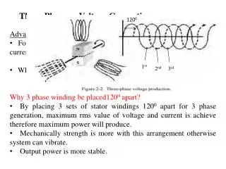
Plug Braking Power Schematic same as reversing DOL starter Two phases are swapped over until motor stops. A centrifugal switch, speed sensing relay or timer used to prevent the motor from reversing. Contactor C2 is for starting Contactor C3 is for stopping WARNING Four times the kinetic energy of load dissipated in stator windings Power Schematic
DC Injection Braking Power Schematic requires DC available at a lower voltage e.g. 50V This can be achieved using a transformer and 4 diodes When required to stop, DC is connected to two of the phases Stator field then becomes stationary Rotor then runs faster than stator field causing a large braking torque in the rotor When rotor stops there is no more braking torque WARNING DC injection braking can burn out the stator windings Control circuit will be the same as for plug braking with timer, centrifugal switch or speed sensing relay Inverters often incorporate this type of braking
DC Injection Braking Run contactor C2 will start the motor as for DOL starter When C3 energises, DC is injected into 2 phases of stator for a short time WARNING DC injection braking can burn out the stator windings if voltage is too high Power Schematic
DC Injection Braking Transformer reduces AC voltage Transformer requires separate fuses Full-wave rectifier converts AC into DC Power Schematic – DC section
DC Injection Braking DC current travels through one phase and back up through another phase Power Schematic – DC injection
DC Injection Braking Press S2 to start as for DOL starter Press S1 to stop as for DOL but C3 will energise for a time WARNING DC injection braking can burn out the stator windings if time is too long This control circuit can be used for PLUG braking also Control Circuit
Speed Ramping Down with an Inverter Inverter required to ramp the frequency of motor supply down to zero Stator field moves slower that rotor causing braking torque Ramp down time can be adjusted within the inverter
Dynamic Braking with Inverter Inverter required to allow kinetic energy in load to be recovered Energy recovered is wasted in resistor RDB switched into circuit by transistor Resistor RDB value determines the stopping time
Regenerative Braking with Inverter Inverter required to allow kinetic energy in load to be recovered Energy recovered is fed back into the mains This methods saves energy and money