Download
1 / 30
320 likes | 508 Views
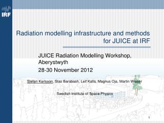
JUICE Rad. Modelling WS 2012 - SPENVIS. H. D. R. Evans Univ. Aberystwyth 28/11/2012. Getting on line. http://www.spenvis.oma.be/. Outline. Introduction to SPENVIS – getting started Generate a mission trajectory Overview of available radiation environment models

E N D
JUICE Rad. Modelling WS 2012 - SPENVIS H. D. R. EvansUniv. Aberystwyth28/11/2012
Getting on line http://www.spenvis.oma.be/
Outline • Introduction to SPENVIS – getting started • Generate a mission trajectory • Overview of available radiation environment models • Use of JOREM models to calculate environment • The various simple effects tools • The Geant4 tools (Mulassis, SSAT, GRAS, GEMAT) • Exporting results
Registration Temporary Accounts available: juice_1 juice_2 … juice_20 Password for each is: juice2012
Create a Project Link to project management Link to Model pages Link to User Profile
User Profile Change to Advanced
Model Home Page Change to Jupiter
A Mission Trajectory is required Three means of specifying the trajectory: • Orbit Generator • Upload trajectory file (SPENVIS format) • Upload CCSDS OEM trajectory file (JOREM extension) • Orbit generator uses ephemera and propagates the orbit • Semi-major axis/eccentricity • Apojove/perijove • Hyperbolic (for fly-by missions) • SPENVIS trajectory upload has format specified in help pages:http://www.spenvis.oma.be/help/models/sapre_upl.html • JOREM Upload available via the JOREM model section
Output Pages Link that can be used by Excel to download CSV formatted data as HTML tables CSV Format defined in help pages
Radiation Models Radiation sources include: • Galactic cosmic rays • Solar protons (long, short term) • Trapped radiation belts (D&G, GIRE, Salammbô) Models for all three sources in the “Radiation Sources and Effects Models” In addition, there are the Jovian specific JOREM models: • Electron belt • Proton belt • Carbon, Oxygen, Sulphur belts • Electron background model (IEM)
Effects Tools • SHIELDOSE-2 Dose as function of shielding thickness (p+, e-) • SHIELDOSE-2Q • Non-Ionising dose NID as function of shielding thickness (p+, e-) (Opto-electronic degradation) • EQFLUX/MC-SCREAM Solar cell degradation models (p+, e-) • CRÈME models SEU rate predictions (GCR, p+) • Geant4 • Mulassis Simple geometries (slab, sphere) • GRAS Complex 3D geometries (GDML) • SSAT Ray tracing/Sector Shielding (GDML) • GEMAT SEU effects in components Generating GDML files
Dose Calculation Components are rated to a dose limit, beyond which they may fail or fade. This limit is commonly established by testing using a Cobalt-60 source – Gamma ray dose (very penetrating). The radiation dose from the space environment is mixed (protons, electrons, cosmic rays), each with varying levels of shielding effectiveness. This rich environment is simplified into a single metric, e.g. TID, NID, etc. It is also necessary to establish how much dose will be received by a component in the environment given the shielding available: • Simple shielding geometries (solid sphere, slab, spherical shell, etc). • Sector shielding analysis • Full physics simulations (Geant4, Fluka, etc.)
Simple Dose Effects Tools SHIELDOSE(2,2-Q) provides dose-depth curves for simple geometries. Similarly, the NIEL model provides non-ionising doses . This is the simplest, and most conservative approach to RHA of a component. Generally, the solid sphere geometry is used and can serve as an input to the sector shielding approach (SSAT, FASTRAD, DOSRAD, etc.)
Upset Calculation - Theory SEE are caused by GCRs and protons SEE can be: destructive, e.g. Latch-up, or temporary, e.g. Single event upset/bit flip Mechanism is species dependent: • Ions: cause upsets via ionization; this depends on the length of the ionization column in the sensitive volume of the component. • Protons: cause upsets via a nuclear interaction leading to an ionization column. Evaluating SEE requires knowledge of component Test data (some component data included in SPENVIS)
Device Test Data Aim is to have a cross section curve as a function of incident particle LET or proton energy. This is typically the data is fit to a Weibull or Bendel function Proton test data No obvious LETth Test saturation cross sectionmatches the visual inspection Heavy Ion test data
Upset Calculation - Ions • CREME 86/96 RPP method: • Device Dimensions (l×w×h) RPP path length distribution. These dimensions are derived from actual device dimension measurements, the cross section test data and device thickness. • Critical Charge (Qc) – proportional to LETth. • Cross section: is from the device test data. N.B.: 22.5 is for Silicon, for GaAs this becomes 30.0
Upset Calculation - Theory • Protons: CREME 86/96 method: Cross-section data (Bendel, Weibull, Profit) In principle, there are no angular effects to consider.
Geant4 Models Geant4 tools have similar inputs • Source particle definitions • Physics lists • Material lists • Geometry (GRAS, SSAT) • Mulassis & GEMAT have theirown geometry definitions. Geant4 input files (macros & GDML) available for download to permit local runs.
Geometry Definition (GDML) Two tools available to generate simple GDML geometries: • HTML based Geometry Definition tool • Series of HTML pages to specify a geometry with up to 10 elements using CSG (sphere, box, cylinder) • Visualisation available at each step using VRML (need plug in, such as Cortona(http://www.cortona3d.com/) • Java Geometry Generation Tool • Downloaded Java application • Interactive visualisation • Upload GDML file from CAD tool,e.g. FASTRAD.
Sector Shielding Doses (SSAT) Run SSAT to derive shielding distribution curve Use SHIELDOSE-2 or SHIELDOSE-2Q and import shielding depths from SSAT. Running SD2(Q) will fold Shielding distribution curve with the Dose-depth curve to provide Dose contribution for each shielding thickness for the geometry. The cumulative curve gives the dose in the target. Look in SSAT GDML file analysis to find location of target (not obvious)
Mulassis • Simple geometries, like Shieldose: • Slab • Spherical shells (solid sphere) • Can be used to investigate graded, or exotic shields and targets. • Outputs include: • Shielded flux spectra • Total Ionising dose • Non-Ionising dose • Pulse height spectrum • Dose Equivalent (Human effects) Recommend using slab geometries, as statistics are better. Although for solid sphere equivalent, an good approximation (~10%) is to use a spherical shell with a vacuum “core” that’s 1/10th the thickness of shield.
GRAS Complex 3D analysis module Geometry defined by GDML file Targets selected from GDML file Can use the SPENVIS system to set up a basic run, download the input files and run more detailed analysis locally. SPENVIS limits model runs to 600s, Which can often be insufficient for a complex geometry to be analysed with adequate statistics.
GEMAT • Used to study the effects of radiation on micro-electronics (Single Event Effects). • A geometry is defined for a component in terms of layers. Using common shapescylinder, box, “L” and “U” shapes • Analysis of • incident flux • Pulse height • Allows analysis of morecomplex geometries thanprovided by CREME.
JOREM tools • SHIELDOSE-2Q • Same methods as SHIELDOSE-2 • Energies of electrons extended • More shielding compositions (Al, Ti, Fe, Ta, CW80, Al+Ta dual layer) • More target materials. • Genetic Algorithm for shielding optimisation • Uses GA to optimise shielding layered geometries • Fitness function based on mass, thickness, TID, NID. • Particle spectra from Environment models. • Moon Environment analysis (Planetocosmics-J)
Advice • The SPENVIS system, being an on-line system, limits model runs to only 600 CPU seconds. • The JOREM Radiation models can take a significant time to run – sample the orbit of interest, use a single orbit at, e.g. Ganymede. Don’t try to simulate the entire mission with a 60s time resolution. • Normally only 2 projects are provided to users, this can be increased by request to the SPENVIS team • Similarly, CPU limits and disk usage can be extended beyond the default on request. • Forums are available for assistance. • ECSS Standard Resources: • ECSS-E-ST-10-12C: valuable resource for determining effects • ECSS-Q-ST-60-15C: Radiation Hardness Assurance standard • For RHA – a margin of a factor of 2 should suffice.