Download
1 / 64
650 likes | 760 Views
Archaeological Land Use Characterization using Multispectral Remote Sensing Data. UNIVERSIDAD DE GUADALAJARA CENTRO UNIVERSITARIO DE LOS VALLES. Dr. Iván Esteban Villalón Turrubiates, Member, IEEE María de Jesús Llovera Torres.

E N D
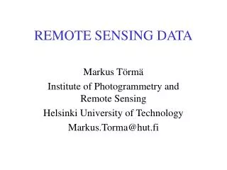
Archaeological Land Use Characterization using Multispectral Remote Sensing Data UNIVERSIDAD DE GUADALAJARA CENTRO UNIVERSITARIO DE LOS VALLES Dr. Iván Esteban Villalón Turrubiates, Member,IEEE María de Jesús Llovera Torres Monitoring Hidrological Variations using Multispectral SPOT-5 Data: Regional Case of Jalisco in Mexico Dr. Iván Esteban Villalón Turrubiates, Member,IEEE
Overview • Abstract • Remote Sensing Definition • Sensor Resolution • Introduction to Image Classification • Model Formalism • Verification Protocols • Simulation Experiments • Concluding Remarks
Abstract • Proposition - A new and efficient classification approach of remote sensing signatures extracted from large-scale multispectral imagery. • Contribution -This approach exploits the idea of combining the spectral signatures from a remote sensing image to perform a novel and accurate classification technique. • Verification -Simulation results are provided to verify the efficiency of the proposed approach.
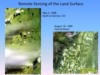
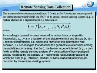
Remote Sensing • Remote Sensing can be defined as: • "The arte and science to obtain data from an object avoiding direct contact with it” (Jensen 2000). • There is a transmission medium involved?
Remote Sensing • Of the Environment: • … is the collection of information regarding our Planet surface and its phenomena involving sensors that are not in direct contact with the studied area. The main focus is in recollected information from a spatial perspective throughout electromagnetic radiation transmission.
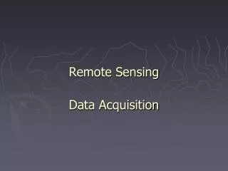
Remote Sensing • Sensor election. • Reception, storage and digital signal processing of the data. • Analysis of the resulting information.
Process A) Illumination Source B) Radiation C) Interaction with the object D) Radiation sensing E) Transmission, reception and data processing F) Analysis and interpretation G) Application
Resolution • All remote sensing systems use four types of resolution: • Spatial • Spectral • Temporal • Radiometric
Temporal Resolution July 2 July 8 August 3 16 days Time 11 days July 1 July 23 August 3 July 12
Radiometric Resolution 6-bits Range 0 63 8-bits Range 0 255 10-bits Range 0 1023
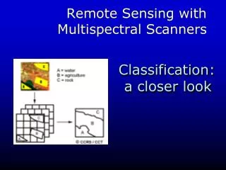
Image Classification • Why classify? • Make sense of a landscape • Place landscape into categories (classes) • Forest, Agriculture, Water, Soil, etc. • Classification scheme = structure of classes • Depends on needs of users.
Typical uses • Provide context • Landscape planning or assessment • Research projects • Natural resources management • Archaeological studies • Drive models • Meteorology • Biodiversity • Water distribution • Land use
Example: Near Mary’s Peak • Derived from a 1988 Landsat TM image • Distinguish types of forest Legend Open Semi-open Broadleaf Mixed Young Conifer Mature Conifer Old Conifer
Classification: Critical Point • LAND COVER not necessarily equivalent to LAND USE • We focus on what’s there: LAND COVER • Many users are interested in how what is there is being used: LAND USE • Example • Grass is land cover; pasture and recreational parks are land uses of grass
Basic Strategy: How to do it? • Use radiometric properties of remote sensor • Different objects have different spectral signatures
Basic Strategy: How to do it? • In an easy world, all “vegetation” pixels would have exactly the same spectral signature. • Then we could just say that any pixel in an image with that signature was vegetation. • We could do the same for soil, water, etc. to end up with a map of classes.
Basic Strategy: How to do it? But in reality, that is not the case. Looking at several pixels with vegetation, you’d see variety in spectral signatures. The same would happen for other types of pixels, as well.
The Classification Trick: Deal with variability • Different ways of dealing with the variability lead to different ways of classifying images. • To talk about this, we need to look at spectral signatures a little differently.
Think of a pixel’s brightness in a 2-Dimensional space. The pixel occupies a point in that space. The vegetation pixel and the soil pixel occupy different points in a 2-D space.
With variability, the vegetation pixels now occupy a region, not a point, of n-Dimensional space. Soil pixels occupy a different region of n-Dimensional space.
Basic Strategy: Deal with variability • Classification: • Delineate boundaries of classes in n-dimensional space • Assign class names to pixels using those boundaries
Classification Strategies • Two basic strategies: • Supervised Classification • We impose our perceptions on the spectral data. • Unsupervised Classification • Spectral data imposes constraints on our interpretation.
Conifer Deciduous Water Digital Image Supervised Classification Supervised classification requires the analyst to select training areas where he knows what is on the ground and then digitize a polygon within that area… Mean Spectral Signatures The computer then creates... Known Conifer Area Known Water Area Known Deciduous Area
Conifer Deciduous Unknown Water Supervised Classification Information Mean Spectral Signatures Multispectral Image (Classified Image) Spectral Signature of Next Pixel to be Classified
The Result: Image Signatures Land Cover Map Legend: Water Conifer Deciduous
Unsupervised Classification • In unsupervised classification, the spectral data imposes constraints on our interpretation. • How? Rather than defining training sets and carving out pieces of n-Dimensional space, we define no classes beforehand and instead use statistical approaches to divide the n-Dimensional space into clusters with the best separation. • After the fact, we assign class names to those clusters.
Cluster 3 Cluster 5 Cluster 6 Cluster 2 Cluster 1 Cluster 4 Spectrally Distinct Clusters Unsupervised Classification The analyst requests the computer to examine the image and extract a number of spectrally distinct clusters… Digital Image
Cluster 3 Cluster 5 Cluster 6 Cluster 2 Unknown Cluster 1 Cluster 4 Saved Clusters Next Pixel to be Classified Unsupervised Classification Output Classified Image
Labels Land Cover Map Water Legend Water Conif. Water Conifer Hardw. Conifer Hardwood Hardwood Unsupervised Classification The result is essentially the same as that of the supervised classification: It is a simple process to regroup (recode) the clusters into meaningful information classes (the legend).
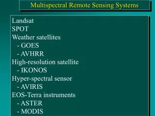
Multispectral Imaging • Is a technology originally developed for space-based imaging. • Multispectral images are the main type of images acquired by remote sensing radiometers. • Usually, remote sensing systems have from 3 to 7 radiometers; each one acquires one digital image in a small band of visible spectra, ranging 450 to 690 nm, called red-green-blue (RGB) regions: • Blue -> 450-520 nm. • Green -> 520-600 nm. • Red -> 600-690 nm. • The combination of the RGB spectral bands generates the so-called True-Color RS images.
Weighted Pixel Statistics Method • Statistical Approach. • Assume normal distributions of pixels within classes. • For each class, build a discriminant function • For each pixel in the image, this function calculates the probability that the pixel is a member of that class. • Takes into account mean and variance of training set. • Each pixel is assigned to the class for which it has the highest probability of membership.
Weighted Pixel Statistics Method Mean Signature 1 Candidate Pixel Relative Reflectance Mean Signature 2 It appears that the candidate pixel is closest to Signature 1. However, when we consider the variance around the signatures… Blue Green Red Near-IR Mid-IR
Weighted Pixel Statistics Method Mean Signature 1 Candidate Pixel Relative Reflectance Mean Signature 2 The candidate pixel clearly belongs to the signature 2 group. Blue Green Red Near-IR Mid-IR
Verification Protocols • A set of three synthesized images are used as verification protocols. • All synthesized images are True-Color (RGB), presented in 1024-by-1024 pixels (TIFF format). • Each synthesized image contains three different regions (in yellow, blue and black colors) with a different pattern. • The developed Weighted Pixel Statistics (WPS) algorithm is compared with the most traditional Weighted Order Statistics (WOS) method [S.W. Perry, H.S. Wong, 2002].
Results:1st Synthesized Scene Synthesized Scene WOS Classification WPS Classification
Results:2nd Synthesized Scene Synthesized Scene WOS Classification WPS Classification
Qualitative Comparison2nd Synthesized Scene Synthesized Scene WOS Classification WPS Classification